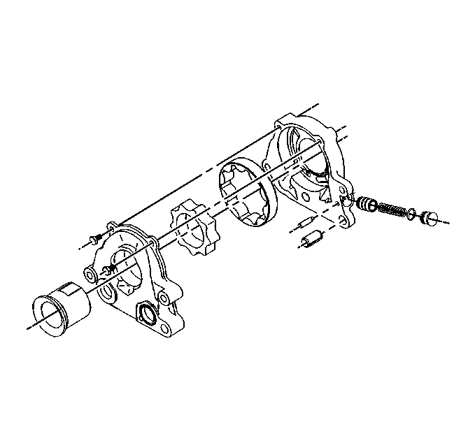
- Disassemble the oil pump using the following procedure:
| 1.1. | Remove the drive spacer from the oil pump housing. |
| 1.2. | Remove the two screws holding the pump housing halves together. |
| 1.3. | Remove the inner (drive) and the outer (driven) rotors from the
housing. Mark the mating surfaces. The outer rotor has one chamfered edge.
The outer rotor should be installed in the pump body (1) with the chamfered
edge facing the rear of the pump. |
| 1.4. | Remove the oil pressure relief valve as follows: |
| 1.4.1. | Remove the pressure relief valve cap retaining pin. |
| 1.4.2. | Remove the retaining plug without damaging the o-ring seal. |
| 1.4.3. | Slide the pressure relief valve spring and piston out of its bore. |
| 1.5. | Clean the oil pump components in solvent. |
- Inspect the oil pump components for the following conditions:
Important: The internal parts of the oil pump are not serviced separately. If wear
or damage is noted, replace the entire pump assembly.
| • | The housing and the cover for cracks, scoring, casting imperfections,
and damaged threads. |
| • | The rotor gears for chipping, galling or wear. |
| • | Pressure relief valve piston for embedded particles and/or damage. |
| • | Pressure relief valve bore for scoring and smooth piston movement. |
- Assemble the oil pump using the following procedure:
| 3.1. | Install the inner and the outer rotors in the pump cover in the
same orientation as removed. |
| 3.2. | Install the pressure relief piston, spring and retaining cap in
the pump housing bore. |
| 3.3. | Install the pressure relief valve cap retaining pin. |
| 3.4. | Pack the pump housing with white petroleum jelly to ensure pump
priming. |
| 3.5. | Assemble the housing and cover over the locating dowel. |
| 3.6. | Insert a 3/8 in. (9.5 mm) drill in the pump mounting
hole on the opposite side in order to aid in the alignment of the housing
and cover. |
| 3.7. | Install the two retaining screws. |
Tighten
Tighten the screws to 12 N·m (106 lb in).
Notice: Use the correct fastener in the correct location. Replacement fasteners
must be the correct part number for that application. Fasteners requiring
replacement or fasteners requiring the use of thread locking compound or sealant
are identified in the service procedure. Do not use paints, lubricants, or
corrosion inhibitors on fasteners or fastener joint surfaces unless specified.
These coatings affect fastener torque and joint clamping force and may damage
the fastener. Use the correct tightening sequence and specifications when
installing fasteners in order to avoid damage to parts and systems.

