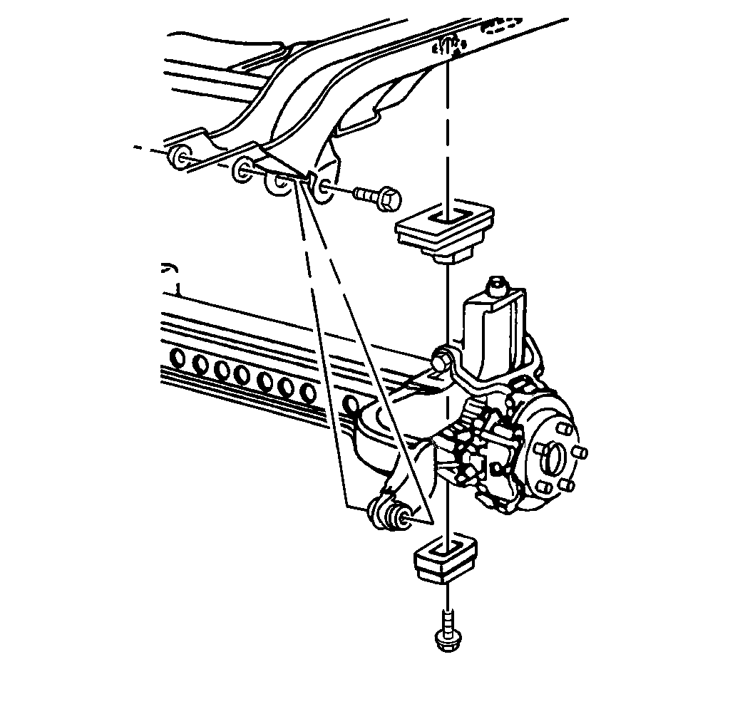
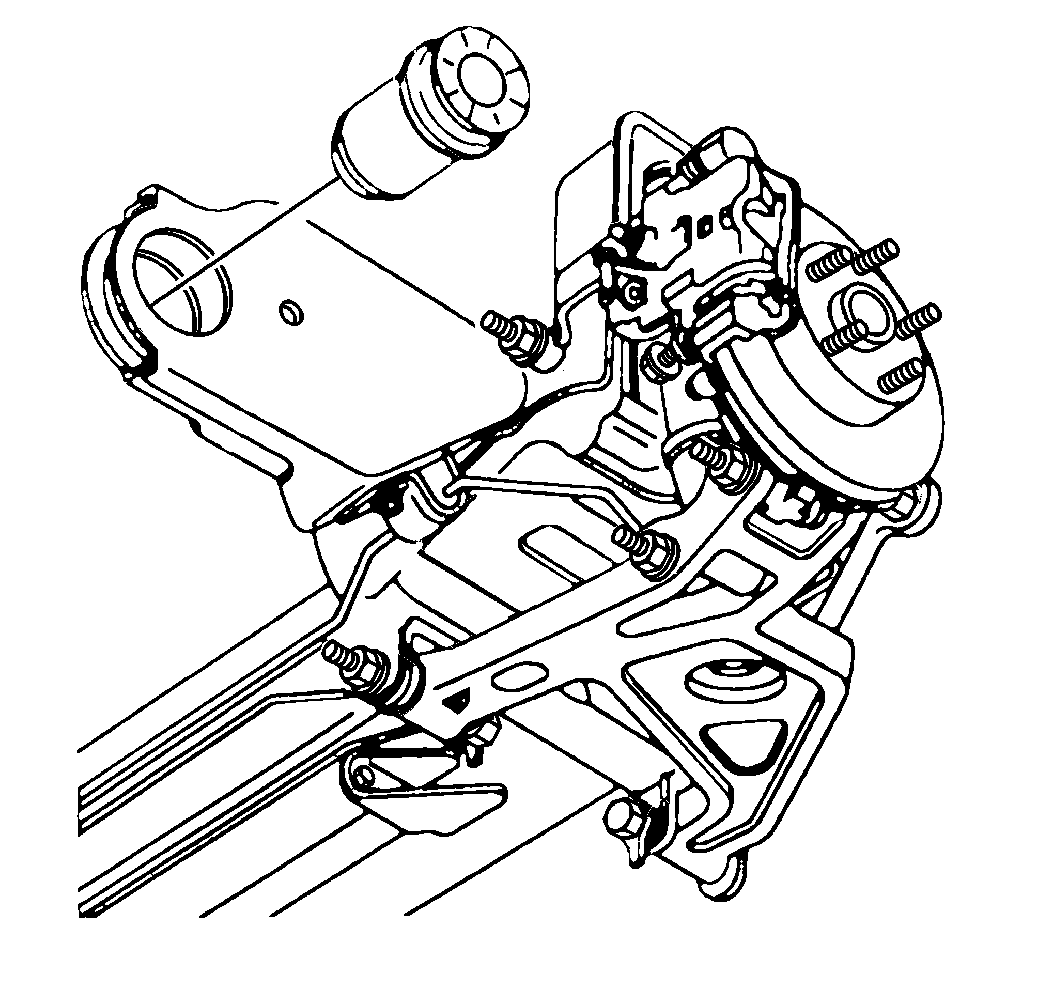
Removal Procedure
The suspension support is a separate sub-frame which supports all of
the other rear suspension components. The suspension support is attached to
the body at four points. The suspension support can be removed from the
vehicle without removing or disconnecting the following parts:
| • | The hub and bearing assembly |
Important: Since the right rear brake crossover pipe is mounted to the suspension
support, it is important that all necessary precautions described in the following
procedure are taken in order to ensure that the pipe is not damaged during
the suspension support removal or installations procedures.
- Raise and support the vehicle. Refer to
Lifting and Jacking the Vehicle
in General Information.
- Remove the tires and wheels. Refer to
Tire and Wheel Removal and Installation
in Tires and Wheel.

- Suspend the left caliper.
Refer to
Rear Brake Caliper Replacement
in Disc Brakes.
- Remove the other rear suspension components as required.

- Remove the intermediate
parking brake cable from the equalizer (2) and move the intermediate
cable clear of the suspension support.
- Remove the rear brake crossover pipe and the left rear brake hose
from the bracket.
- Disconnect the rear chassis wiring harness from the main body
wiring harness.
- Support the rear suspension support with suitable jackstand.

- Remove the suspension
support forward arm bolts, upper mounting bolts and lower insulators.
Important: While lowering the support, carefully watch the position of the brake
calipers, brake hoses and crossover pipes in order to prevent damage during
the removal procedure.
- Lower the jackstand.
Installation Procedure

- Position the suspension
support under the vehicle on suitable jackstand. Align the suspension support
with the vehicle body directly below the installed position.
- Install the upper suspension support insulators on the suspension
support.
Notice: Use the correct fastener in the correct location. Replacement fasteners
must be the correct part number for that application. Fasteners requiring
replacement or fasteners requiring the use of thread locking compound or sealant
are identified in the service procedure. Do not use paints, lubricants, or
corrosion inhibitors on fasteners or fastener joint surfaces unless specified.
These coatings affect fastener torque and joint clamping force and may damage
the fastener. Use the correct tightening sequence and specifications when
installing fasteners in order to avoid damage to parts and systems.
Important: While raising the suspension support, carefully watch the position of
the brake calipers, brake hoses and crossover pipes. Reposition the brake
calipers, brake pipes, and brake hoses as required in order to prevent interference
or damage to the brake components.
- Slowly raise the suspension support into the vehicle. Align the suspension
support with the vehicle body as it is raised.
Important:
| • | Install both forward arm bolts in the proper direction, with the
nuts installed on the right side of the arm. |
| • | The cup-shaped washer is used on the left forward arm bolt installation
only. |
- Install the suspension support forward arm bolts, nuts and washers,
upper mounting bolts and insulators.
Tighten
| • | Tighten the right side suspension support forward arm nut to 63 N·m
(46 lb ft). |
| • | Tighten the left side suspension support forward arm bolt to 102 N·m
(75 lb ft). |
| • | Tighten the upper mounting bolts to 102 N·m (75 lb ft). |
- Connect the rear chassis wiring harness to the main body wiring
harness.
- Install the left rear brake hose and crossover pipe to the bracket.
- Bleed the brakes. Refer to
Hydraulic Brake System Bleeding
in Hydraulic Brakes.

- Connect the intermediate
parking brake cable to the equalizer (2).
- Install any other rear suspension components previously removed.
- Install the left caliper and the new caliper mounting bracket
bolts. Refer to
Rear Brake Caliper Replacement
in Disc Brakes.
Tighten
| • | Tighten the caliper mounting bracket bolts to 113 N·m
(83 lb ft). |
| • | Tighten the parking brake cable bracket bolt to 43 N·m
(32 lb ft). |
- Install the tire and wheel assemblies. Refer to
Tire and Wheel Removal and Installation
in Tires and Wheel.
Important: Before lowering the vehicle onto its wheels (or before driving the vehicle,
if it was not on a lift) turn the ignition on and wait approximately 45 seconds.
This will permit the ALC system to execute the ARC, ensuring that the air
adjustable shock absorbers are filled with residual pressure.
- Lower the vehicle.


