Rear Rail Replacement Crossbar
Removal Procedure

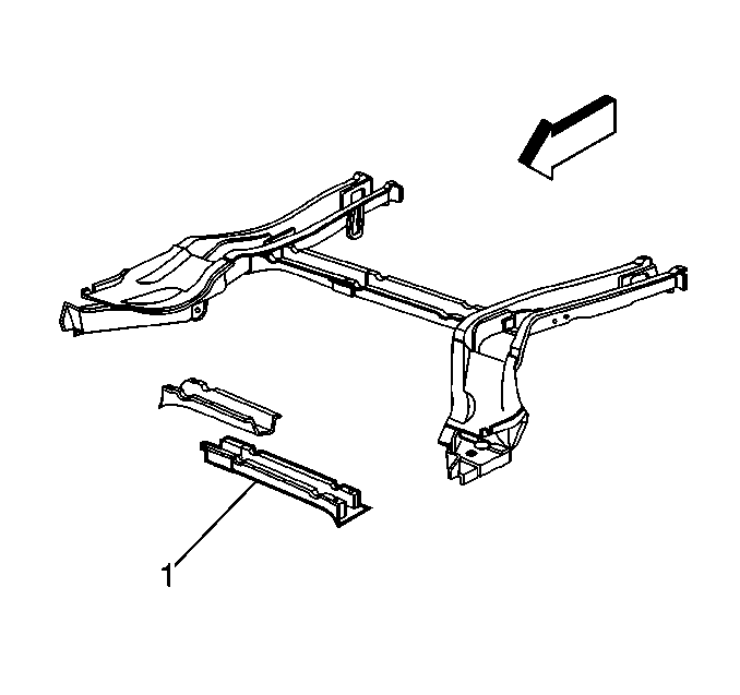
Important: The rear crossbar connects the two rear rails for added strength and
rigidity (1) consists of two pieces, a left and right side, that can be ordered
separately. The crossbar should only be replaced at factory seams.
- Remove all related panels and components.
- Visually inspect and restore as much of the damage as possible
to factory specifications.
- Remove the following as necessary:
| • | Anti-corrosion materials |
- Locate, mark and drill out all factory welds. Note the number
of welds for installation of the crossbar service part.
- Remove the damaged crossbar.
Installation Procedure

- Prepare mating surfaces.
- Check for proper fit of the service part (1).
- Drill 8 mm (5/16 in) plug weld holes on the service
part as necessary in the locations noted from the original assembly.
- Position the service part.
- Check fit of body dimensions. Use three-dimensional measuring
equipment.
- Plug weld accordingly.
- Clean and prepare welded surfaces.
- Prime with two-part catalyzed primer.
Important: Prior to refinishing, refer to GM 4901MD-99 Refinish Manual for
recommended products. Do not combine paint systems. Refer to paint manufacturer's
recommendations.
- Apply sealers and anti-corrosion materials as necessary.
- Install all related panels and components.
Rear Rail Replacement Full
Removal Procedure

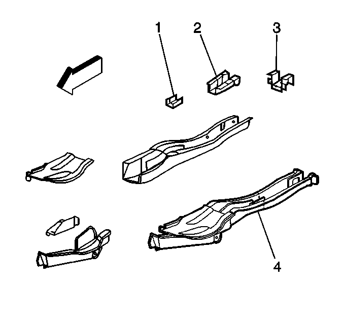
- The left and right rails
are available as complete sub-assemblies. Each consists of outer panels (4),
rear reinforcement (2), inner reinforcements (1) and all necessary
component mounting brackets. The rear extension (3), rear reinforcement
and mounting brackets are also available separately and be easily serviced
at factory seams.The rear extension is also included with the rear end
panel service assembly. Additionally, sectioning procedures can be used
to repair the portion of the rail rearward of the crossbar.
Remove all related panels and components including the rear suspension
and seat.
- Visually inspect and restore as much of the damage as possible
to factory specifications.
- Remove the following as necessary:
| • | Anti-corrosion materials |
- Locate, mark and drill out or chisel all factory welds. Note the
number of welds for installation of the service assembly.
- Remove the damaged rear rail assembly.
Installation Procedure

- Prepare mating surfaces.
- Check for proper fit of the rear rail service assembly.
- Drill 8 mm (5/16 in) plug weld holes on the service
assembly in the locations noted from the original assembly.
- Position the service assembly. Each consists of outer panels (4),
rear reinforcement (2), inner reinforcements (1) and all necessary
component mounting brackets. The rear extension (3), rear reinforcement
and mounting brackets are also available separately and be easily serviced
at factory seams.The rear extension is also included with the rear end
panel service assembly.
- Check to ensure proper fit. Use three-dimensional measuring equipment.
- Plug weld accordingly.
- Clean and prepare welded surfaces.
- Prime with two-part catalyzed primer.
Important: Prior to refinishing, refer to GM 4901MD-99 Refinish Manual for
recommended products. Do not combine paint systems. Refer to paint manufacturer's
recommendations.
- Apply sealers and anti-corrosion materials as necessary.
- Install all related panels and components.


