For 1990-2009 cars only
Outer Door Frame Sectioning General
Removal Procedure

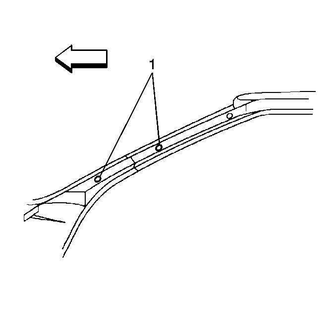
Important: When sectioning areas other than the hinge pillar, a 100 mm (4 in) wide backing plate must be installed behind the joint to ensure a solid and secure weld. Backing plates can usually be cut from the unused portion of the service part or the damaged section of the door frame opening. The A Pillar should be sectioned halfway between the two bottom trim mounting holes (1).
- Remove all related panels and components.
- Remove the following as necessary:
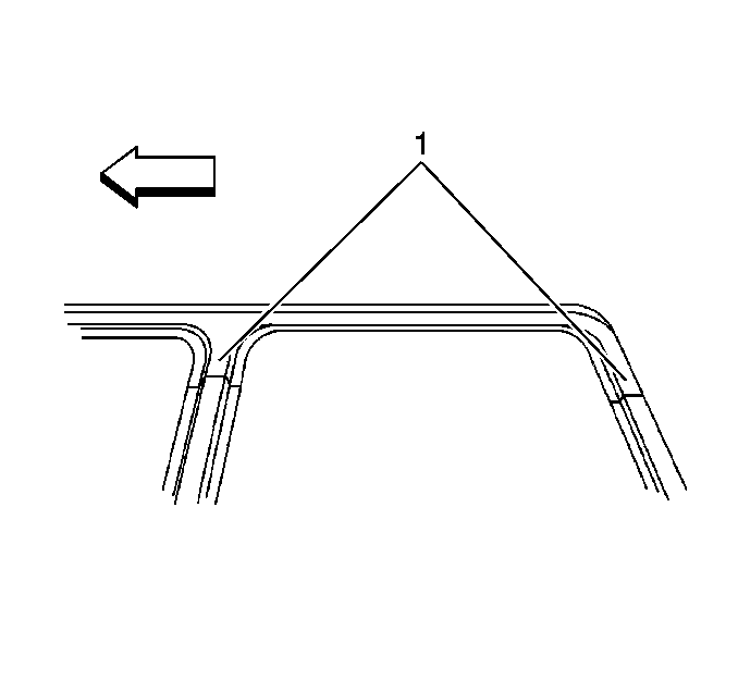
- Section the B and C Pillars along the factory laser weld seams toward the top of the pillars (1).
- Mark cut lines at the recommended locations for sectioning.
- Select the specific areas to be sectioned based upon the extend of damage to the door ring.
- Cut the panels to be sectioned. Take care not to damage any inner panels.
- Locate, mark and drill out all necessary factory welds. Note the number of welds for installation of the service section.
- Remove the damaged section of the door frame opening.
| • | Sealers |
| • | Sound deadeners |
| • | Anti-corrosion materials |


Important: Sectioning is only recommended for the outer panels. If an inner panel is damaged, it must be replaced at the factory seams.
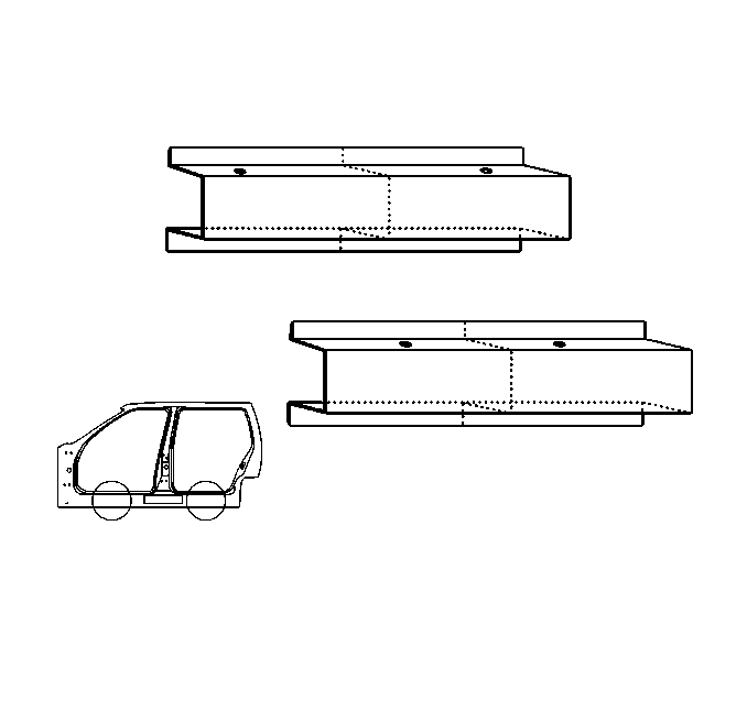
The rocker panels should be sectioned halfway between the small holes along the top surface of each door opening. In the front door opening, the two holes are approximately 370 mm (14 5/8 in) apart. The result is a center line of 185 mm (7 5/16 in). In the rear door opening, the two holes are approximately 312 mm (12 1/4 in) apart. The result is a center line of 156 mm (6 1/8 in).Installation Procedure
- Mark cut lines on the service part at the recommended locations for sectioning.
- Cut the panels to be sectioned.
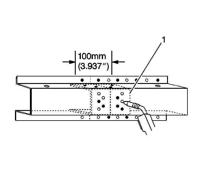
- Cut 100 mm (4 in) sleeves from the unused section of the service part (1).
- Remove the flanges on both sides of this sleeve and modify so that it will fit under the sectioning joint.
- Drill 8 mm (5/16 in) plug weld holes on the service part in the locations noted from the original section.
- Drill plug weld holes along the sectioning cuts on both the service part and the remaining original panels. the plug weld holes should be approximately 25 mm (1 in) from the edge of the cuts.
- Prepare mating surfaces.
- Slide the sleeves 50 mm (2 in) beneath the remaining original panels.
- Position the service part.
- Leave 50 mm (2 in) overlap exposed.
- Check fit of body dimensions. Use three dimensional measuring equipment.
- Plug weld accordingly.
- Stitch weld along the sectioning joints.
- Make 25 mm (1 in) welds along the seam. Leave 25 mm (1 in) gaps between.
- Go back and complete the stitch weld. This will create a solid joint with minimal heat distortion.
- Clean and prepare welded surfaces.
- Prime with two-part catalyzed primer.
- Apply sealers and anti-corrosion materials as necessary.
- Install all related panels and components.

Important: Prior to refinishing, refer to GM 4901MD-99 Refinish Manual for recommended products. Do not combine paint systems. Refer to paint manufacturer's recommendations.
