BODY SERVICE PROCEDURE SERVICE MANUAL UPDATE

MODELS AFFECTED: 1987 FLEETWOOD SIXTY SPECIAL, BODY 6CS19
Some service information regarding the 1987 Fleetwood Sixty Special (extended body) vehicle was not included in the 1987 Body Service Manual. This bulletin provides that information and is intended to supplement the Body Service Manual.
INDEX
Component Page
EXTERIOR TRIM AND ORNAMENTATION
Exterior Door Panel Emblems.......................... 2 Door Lace and Lace Retainer ......................... 2 Front or Rear Door Vinyl Cover ...................... 4 Rocker Molding Outer Trim Panel ..................... 5
INTERIOR TRIM AND ACCESSORIES
Rear Vanity Housing................................. 5 Headlining ......................................... 6 Rear Seat Footrest ................................. 7 Rear Floor Carpet................................... 8 Door Upper lnner Trim Panel ........................ 9
FABRIC ROOF COVER
Vinyl Cover and Foam Pad............................ 9
EXTERIOR TRIM AND ORNAMENTATION
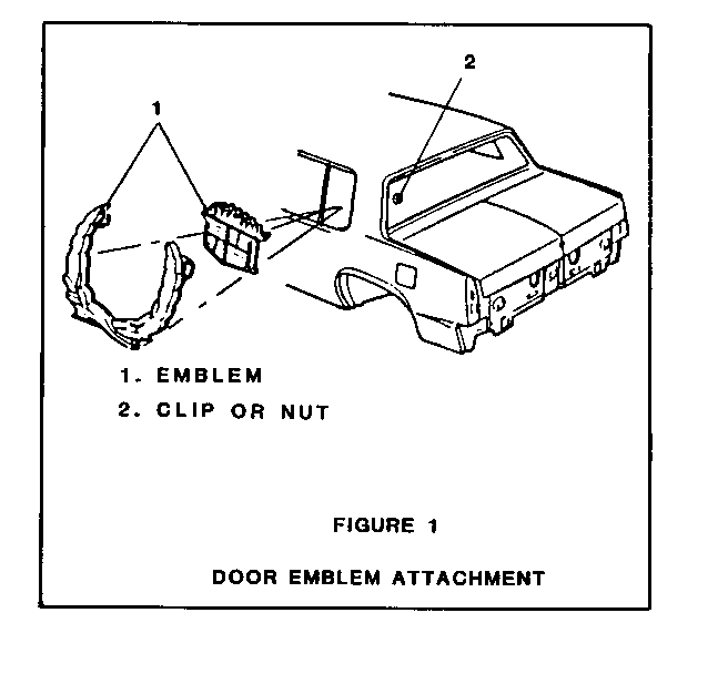
Exterior Door Panel Emblems (Figure 1) on Exterior Door Panel
The exterior door panel emblems have integral studs that snap into retaining clips, or that are retained by nuts. Clip retained emblems may be removed by use of a flat bladed tool used to work the stud out of the clip. Nut retained emblems will require removal of the upper quarter trim panel to gain access to the nuts. installation of the latter type emblems also requires sealing of mounting holes with a medium-bodied sealer.
Remove or Disconnect:
1. Retaining clip or nut 2. Emblem
Install or Connect:
Install reverse of removal and seal as required.
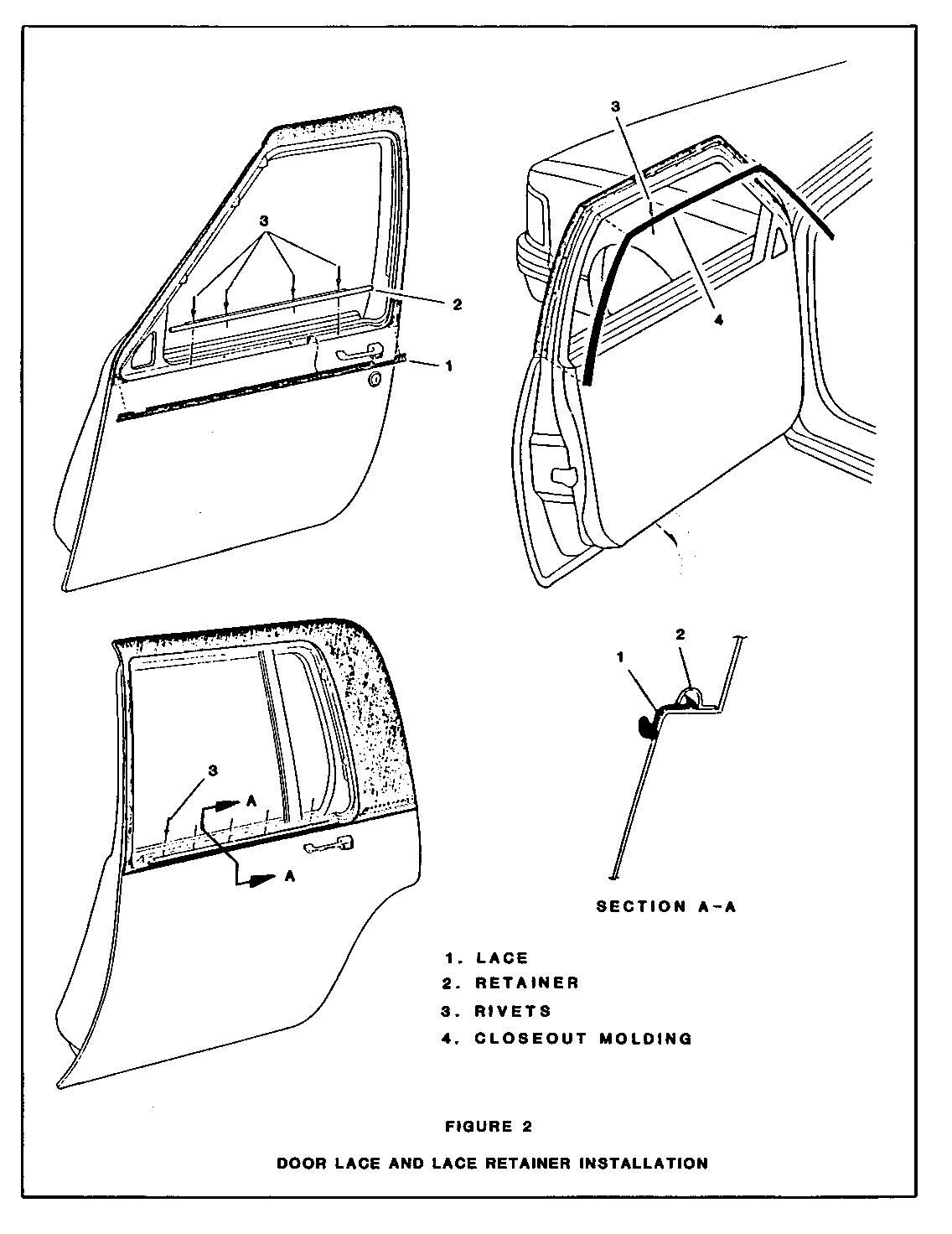
Door Lace and Lace Retainer (Figure 2)
Remove or Disconnect:
1. Front door window frame opening molding assembly (ref. Section 5C of Body Service Manual).
2. Drill out rivets from lace retainers.
3. Lace . Install or Connect: ------------------
Install reverse of removal procedure.
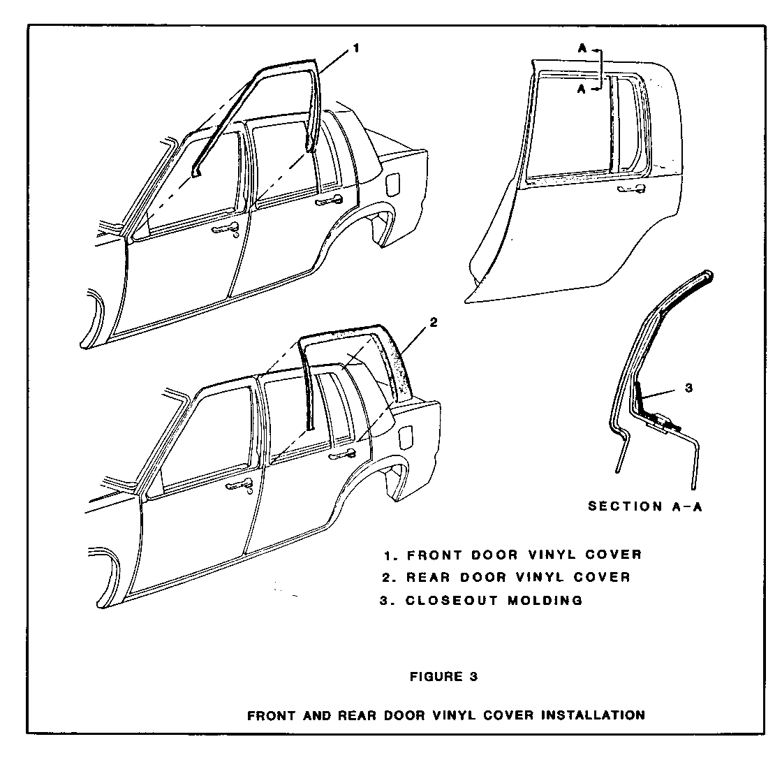
Front or Rear Door Vinyl Cover (Figure 3)
Remove or Disconnect:
1. Door window frame opening molding (ref. Section 5C, Body Service Manual) and door closeout molding (Figure 2, item 4).
2. Apply heat to edges of door vinyl cover (Figure 3) to aid in loosening cover assembly. Heat can be applied with a hot air gun held about 25mm (1") from the cover assembly and rotated in a circular motion. Heat lamps may also be used. if held a minimum of 457mm (18") from the cover assembly.
IMPORTANT:
The use of excessive heat (over 93 degrees C or 200 degrees F) can cause the cover to lose its grain, blister or beconie sh-iny.
3. Loosen all cemented surfaces and carefully remove cover assembly from door. A flat bladed tool or plastic wedge may also be used to assist in loosening the cemented surfaces.
Install or Connect:
1. Remove all traces of adhesive from painted surfaces with a silicone wax and grease removing solvent such as Prep-Sol, Acryli-Clean, Sher-Will-Clean or equivalent.
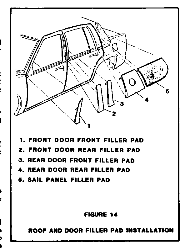
2. Inspect front and rear door foam rubber pads (Figure 14) for damage and replace as necessary.
3. Fit sewn corner(s) of vinyl cover assembly to door and work downward to press in place. Be sure assembly aligns with front and rear edges of door.
4. Complete installation reverse of removal procedure.
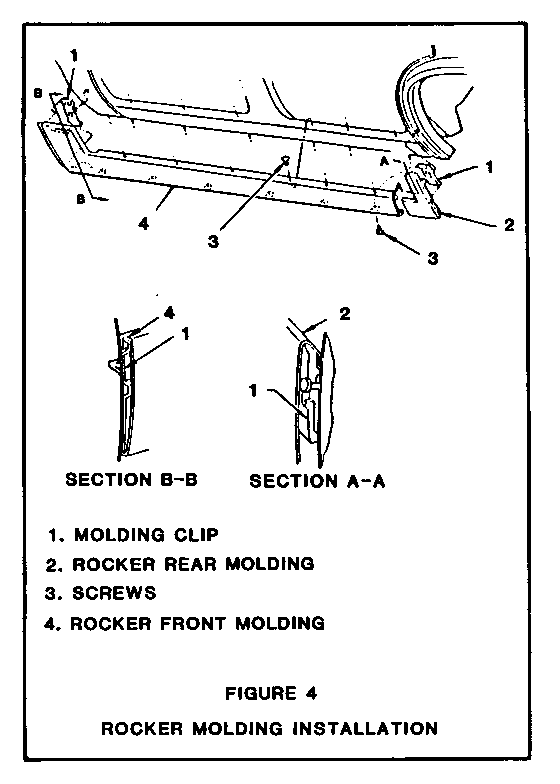
Rocker Molding Outer Trim Panel (Figure 4)
Remove or Disconnect:
1. Molding screws (3).
2. Unsnap front molding (4) from front clip (1) and slide forward to remove.
3. Unsnap rear molding (2).
Install or Connect
Install reverse of removal procedure.
INTERIOR TRIM AND ACCESSORIES
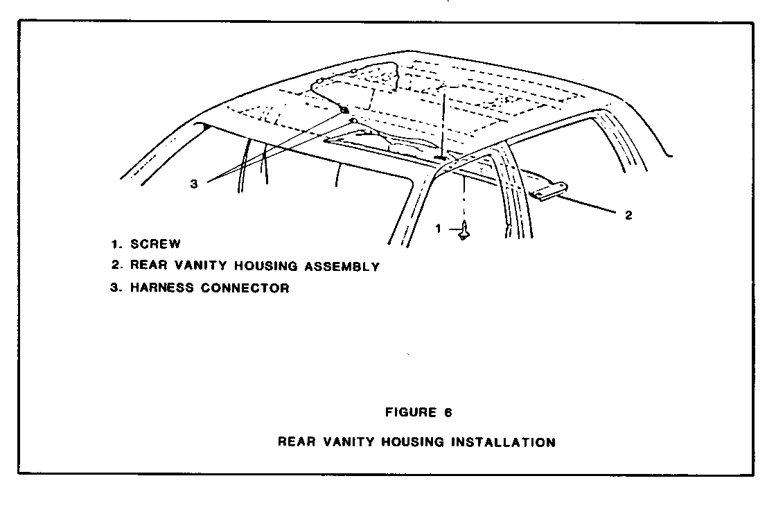
Rear Vanity Housing (Figure 6)
Remove or Disconnect:
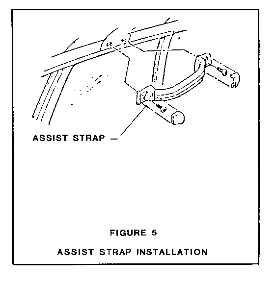
1. Assist straps (Figure 5). 2. Screws (Figure 6, Item 1). 3. Partially lower vanity housing assembly (2), disconnect harness connector (3) and remove assembly.
Install or Connect
Install reverse of removal procedure.
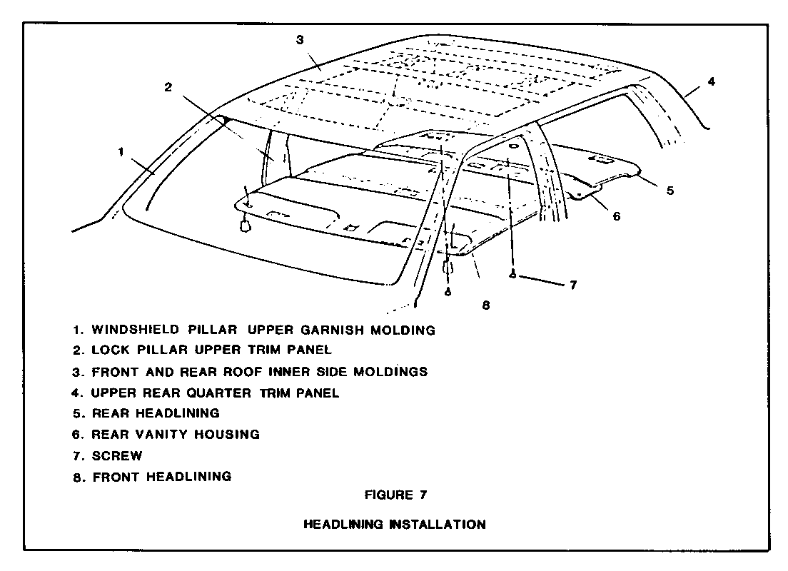
Headlining (Figure 7)
Remove or Disconnect
NOTE: Refer as required to Section 8C in Body Service Manual for detailed 9. Illustrations of components listed.
1. Sunshades and sunshade center support/lamp assembly.
2. Coat hooks.
3. Assist straps (Figure 5).
4. Fiber optic cover assembly.
5. Front and rear roof inner side moldings (Figure 7, Item 3).
6. Windshield pillar upper garnish molding (Figure 7,ltem 1).
7. Lock pillar upper trim (Figure 7, Item 2).
8. Rear window garnish molding.
9. Upper rear quarter panel trim (Figure 7, Item 4).
10. Rear vanity housing (ref. previous paragraph).
11. Recline front seatbacks and position seats as far forward as possible.
12. Release headlining hook and loop fasteners and lower and remove front headlining through right rear door.
13. Similarly remove rear headlining.
Install or Connect:
Install, reverse of removal procedure.
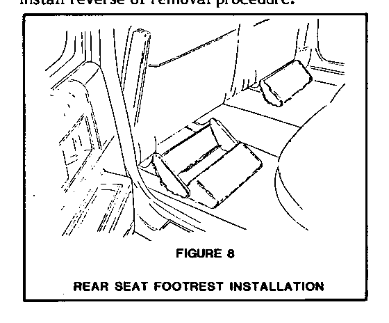
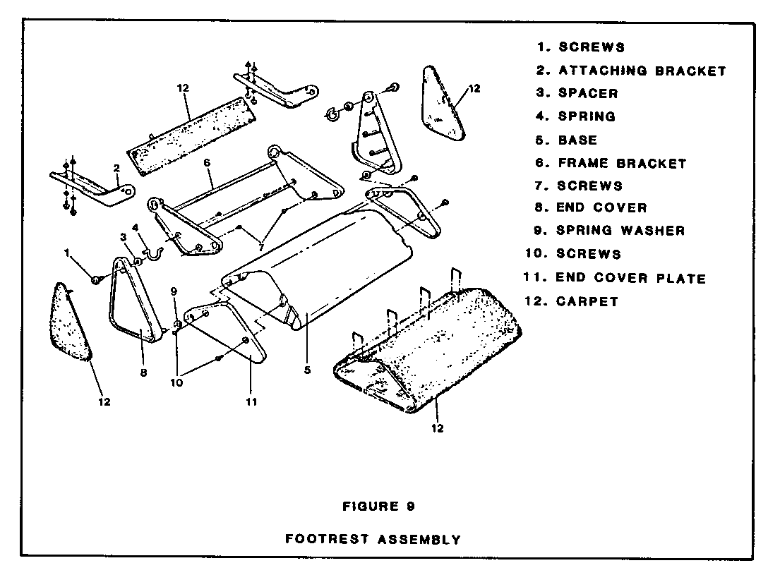
Rear Seat Footrest (Figure 8)
Remove or Disconnect:
1. Position front seats fully forward and raise to full up position.
2. Four bolts from rear of front seat bracket (Figure 9, Item 2 ).
3. Footrest assembly.
Disassemble
1. Peel carpet (Figure 9, Item 12) from end covers (8).
2. Screws (1) from attaching brackets (2).
3. Spacer (3) and spring (4).
4. Pivot base (5) from frame bracket (6).
5. Screws (7) and end cover (8) from frame bracket (6).
6. Base (5) and spring washer (9).
7. Screws (10) and se parate end cover plate (11) from base (5).
Assemble
Assemble reverse of disassembly procedure.
Install or Connect
Install reverse of removal procedure.
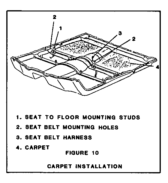
Rear Floor Carpet (Figure 10)
Remove or Disconnect:
NOTE: Refer as required to Sections 8C and 9C in Body Service Manual for detailed illustration and removal procedures for the components listed.
1. Front seat.
2. Rear seat cushion.
3. Front seat belts and floor attachments.
4. Lock pillar upper and lower panel trim.
5. Rear sill plate inserts and sill plates.
6. Lift rear carpet from seat attaching studs (Figure 10, Item 1), feed seat belt harness (3) through opening in carpet and remove carpet.
Install or Connect:
Install reverse of removal procedure and cement carpet at inner rocker panel areas.
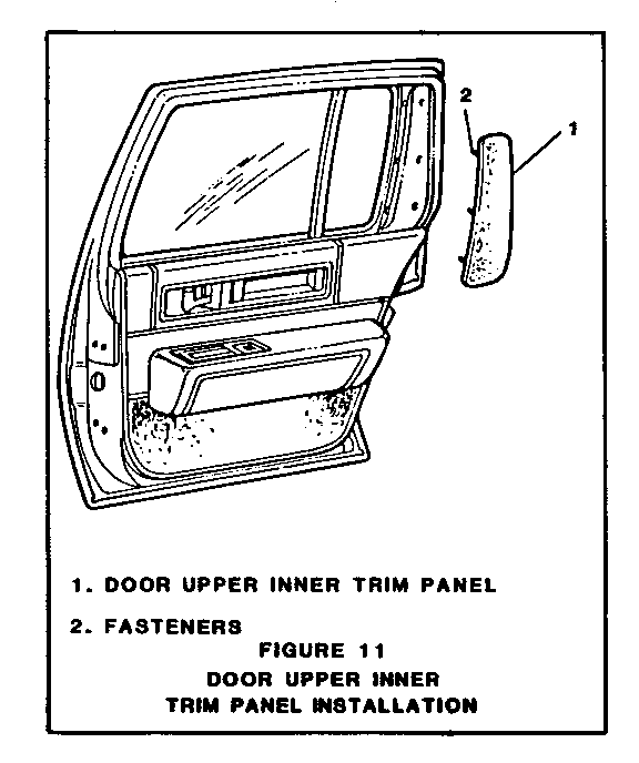
Door Upper Inner Trim Panel (Figure 11)
Remove or Disconnect:
Tools Required:
J24595-B Trim Pad Removal Tool
Using trim pad removal tool J24595-B or equivalent, disengage fasteners (2) of upper door inner trim panel (1) from door.
Install or Connect:
Install reverse of removal procedure.
FABRIC ROOF COVER
NOTE: Refer to Section 8C of Body Service Manual for additional general information as applicable on removal and installation of fabric roof cover and pads.
Vinyl Cover and Foam Pad
Remove or Disconnect
IMPORTANT: To prevent damage to the vehicle paint, mask off all areas immediately adjacent to the fabric cover.
1. Windshield reveal molding.
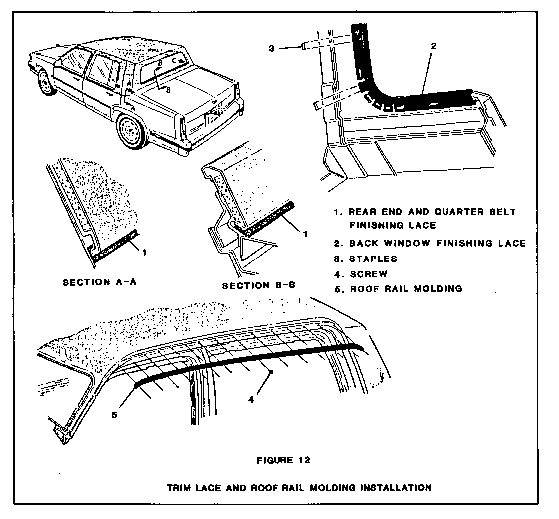
2. Rear end and quarter belt finishing lace (Figure 12, Item 1 .)
3. Tape and break inside loaded rear window glass (ref. Section 2, CB4 Option, Body Service Manual).
4. Unstaple and remove lace around back window opening (Figure 12, Item 2).
5. Roof weatherstripping and roof rail moldings (Figure 12,ltem 5).
6. Apply heat to edges of roof cover to aid in loosening cover. Heat can be applied with a hot air gun held about 25mm (1") from the cover and rotated in a circular motion. Heat lamps may also be used if held a minimum of 457mm (18") from the cover.
IMPORTANT:The use of excessive heat (over 93 degrees C or 200 degrees F) can cause the cover to lose its grain, blister or become shiny.
7. Loosen all cemented edges of vinyl cover, then carefully remove cover and pad from cemented areas of roof panel. A mineral spirit type solyent may be used to loosen the pad along with a putty knife or similar flat- bladed tool.
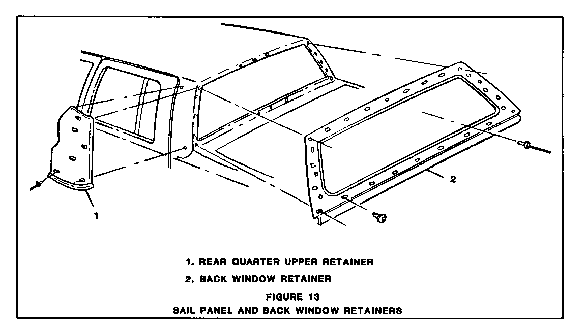
NOTE: The sail panel and back window retainers (Figure 13) are replaceable components available through the normal parts distribution system.
Clean all cemented surfaces of excess cement to ensure a smooth contact surface. Hand wire brush areas where excessive pad or cement is evident. If any metal finishing is performed on the roof panet, repaired area must be painted. directions when
It is not necessary to remove very small bits of cement or padding; however, enough should be removed to prevent highlighting through the roof cover. A mineral spirit type solvent should be used to smooth out excess old cement. Apply solvent and allow to soak before rubbing. Be certain to follow manufacturer's directions when using solvent.
Foam Pad
Install or Connect:
1. Install sail panel foam rubber filler pad (Figure 14, Item 5) and lightly sand upper edges to feather out foam.
2. Using windbreak line at rear of hood, mark centerline of vehicle on upper surface of windshield. Also mark centerline of vehicle on upper surface of back window glass.
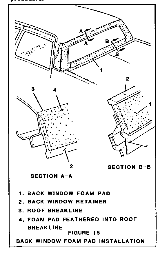
3. Peel protective backing from back window foam pad (Figure 15, Item 1) and position pad onto back window retainer (2).
4. Crease pad firmly into step in shoulder of retainer and trim pad flush with step. Slick trimmed edges into place.
5. Trim pad flush with roof breakline (3).
6. With sandpaper or scrapping tool, contour top edge of foam pad along roof breakline (Figure 15,item 4).
7. Apply pieces of mylar tape to all depressions. Also, apply a continuous length of tape to roof panel indentations at pad to retainer butt joints, and pad to roof panel top edge.
Vinyl Cover
Install or Connect
1. Fold vinyl cover lengthwise at center seam and mark centerline on underside of cover backing.
2. Align cover center seam to centerline of roof and determine proper positioning front-to- rear and amount of overhang.
IMPORTANT: Stretching of pad must be kept to a minimum. Creeping and loss of location may result from excessive stretching.
3. Fold windshield pillar tails and sail panel flaps over center portion of roof cover.
4. Remove release paper from half of cover and stick cover front-to-rear onto roof, starting with center seam and working outward from center. Eliminate all fullness and wrinkles.
IMPORTANT: During slicking operation cover must be lifted and slicked outboard to prevent trapping air under cover. Attempts to correct misaligned or wrinkled conditions may result in damage to the pad.
5. Pull sail panet flap taut and align rear seam of cover to breakline of quarter panel and outboard edge of back window opening. Slick cover in place.
6. Position valance strip cover to pad under back window opening and slick in place.
7. Set tails of cover to windshield pillars and slick in place to pillar facing. Trim end of tail so that approximately a 65mm (2.5") flap remains to the be tucked under the fender corner and cemented to lower end of pillar. Trim excess cover material from door side of windshield pillar so that cover is flush with pinchweld flange.
8. Trim cover at windshield rabbit so that it can be folded down inside wall of rabbit around windshield glass and cemented in place. Edge of cover should be flush with base of windshield rabbit.
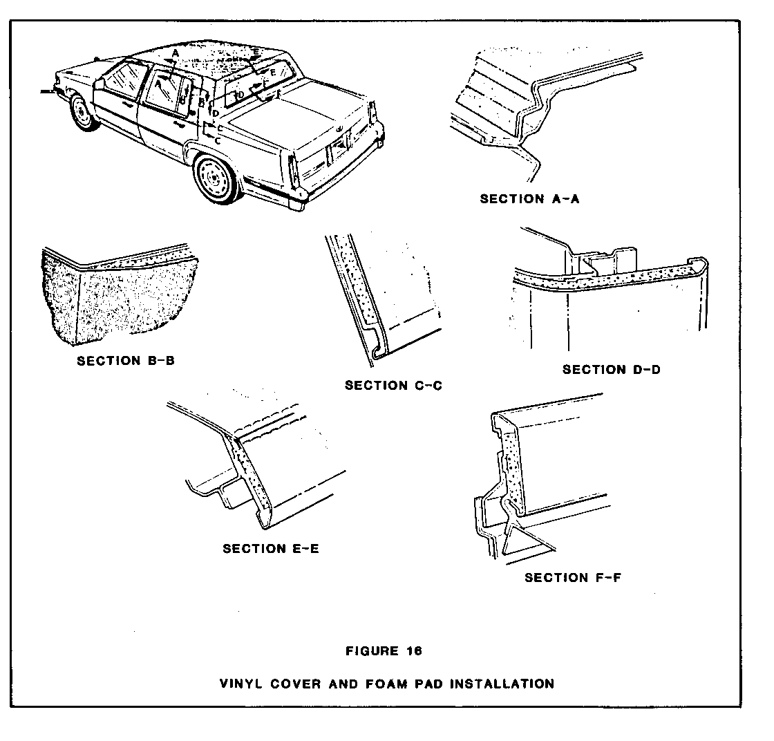
9. Trim excess material at side of roof along pinchweld flange of roof rails (Section A-A, Figure 16).
10. At rear door opening, trim a 20mm (13/16") flap at forward facing of sail panel and slick into place.
11. Trim excess material at quarter and rear end beltlines (Sections C-C and F-F, Figure 16), guilding cutting blade to lace retainers. Tuck material under retainers.
12. Cut away material from back window opening and leave a 22mm (7/8") flap around opening.
13. Cut three notches in flap at four corners of back window opening leaving enough material to wrap over retainer corners. Fold flap around opening.
14. Complete installation reverse of removal procedure.
General Motors bulletins are intended for use by professional technicians, not a "do-it-yourselfer". They are written to inform those technicians of conditions that may occur on some vehicles, or to provide information that could assist in the proper service of a vehicle. Properly trained technicians have the equipment, tools, safety instructions and know-how to do a job properly and safely. If a condition is described, do not assume that the bulletin applies to your vehicle, or that your vehicle will have that condition. See a General Motors dealer servicing your brand of General Motors vehicle for information on whether your vehicle may benefit from the information.
