| Table 1: | A/C Clutch |
| Table 2: | A/C Low Side Temperature Sensor |
| Table 3: | Air Inlet Actuator |
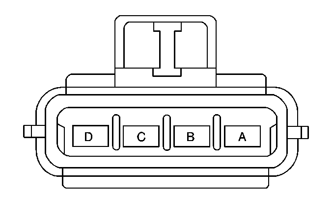
| Table 4: | Ambient Air Temperature Sensor |
| Table 5: | Blower Control Module |
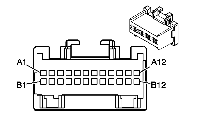
| Table 6: | Instrument Panel Integration Module (IPM) C1 |
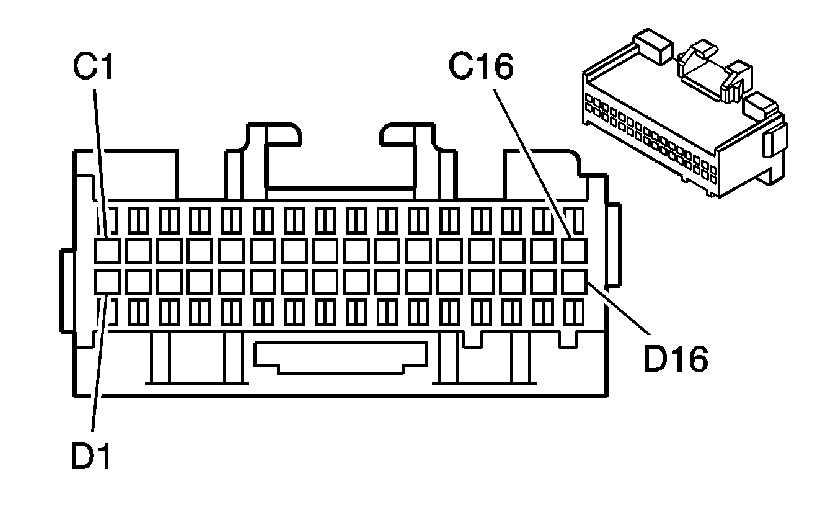
| Table 7: | Instrument Panel Integration Module (IPM) C2 |
| Table 8: | Inside Air Temperature Sensor |
| Table 9: | LH A/C Temperature Sensor |
| Table 10: | LH Inside Air Temperature Sensor |
| Table 11: | LH Sun Load Sensor |
| Table 12: | Mode Actuator |
| Table 13: | RH A/C Temperature Sensor |
| Table 14: | RH Inside Air Temperature Sensor |
| Table 15: | RH Sun Load Sensor |
| Table 16: | Rear Blower Motor |
| Table 17: | Rear Blower Resistor Module |
| Table 18: | Rear Blower Switch |
| Table 19: | Rear Mode Actuator |
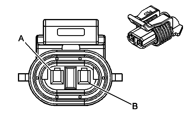
| |||||||
|---|---|---|---|---|---|---|---|
Connector Part Information |
| ||||||
Pin | Wire Color | Circuit No. | Function | ||||
A | DK GRN | 59 | Air Conditioning Compressor Clutch Solenoid Feed | ||||
B | BLK | 1550 | Ground | ||||
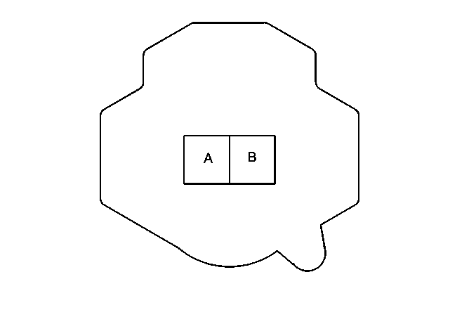
| |||||||
|---|---|---|---|---|---|---|---|
Connector Part Information |
| ||||||
Pin | Wire Color | Circuit No. | Function | ||||
A | BLK | 470 | Sensor Return | ||||
B | GRY | 731 | A/C Refrigerant Low Temperature Sensor Signal | ||||
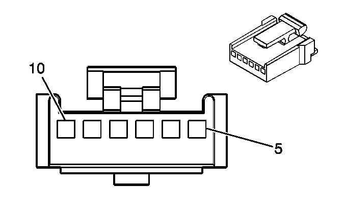
| |||||||
|---|---|---|---|---|---|---|---|
Connector Part Information |
| ||||||
Pin | Wire Color | Circuit No. | Function | ||||
5 | BRN | 141 | Ignition Positive Voltage | ||||
6 | DK GRN | 1614 | Air Inlet Valve Motor Feed | ||||
7 | YEL | 1791 | Air Temperature Valve Motor Return | ||||
8 | -- | -- | Not Used | ||||
9 | PPL | 1838 | Air Inlet Valve Position Sensor Signal | ||||
10 | GRY | 705 | 5 Volt Reference | ||||
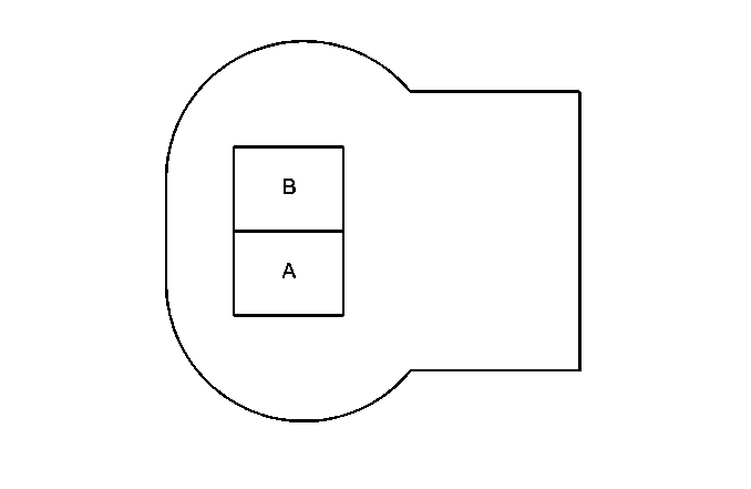
| |||||||
|---|---|---|---|---|---|---|---|
Connector Part Information |
| ||||||
Pin | Wire Color | Circuit No. | Function | ||||
A | LT GRN/BLK | 735 | Ambient Air Temperature Sensor Signal | ||||
B | YEL | 61 | Ambient Air Temperature Sensor Return | ||||
| |||||||
|---|---|---|---|---|---|---|---|
Connector Part Information |
| ||||||
Pin | Wire Color | Circuit No. | Function | ||||
A | BLK | 450 | Ground (LH Drive) | ||||
A | BLK | 350 | Ground (RH Drive) | ||||
B | ORN | 1340 | Ignition Positive Voltage | ||||
C | GRY/BLK | 754 | Blower Speed Signal-Speed Control | ||||
D | -- | -- | Not Used | ||||

| |||||||
|---|---|---|---|---|---|---|---|
Connector Part Information |
| ||||||
Pin | Wire Color | Circuit No. | Function | ||||
5 | BRN | 141 | Ignition Positive Voltage (B+) | ||||
6 | DK BLU | 1199 | Air Temperature Valve Motor Feed | ||||
7 | YEL | 1791 | Air Temperature Valve Motor Return | ||||
8 | -- | -- | Not Used | ||||
9 | LT BLU | 733 | Air Temperature Valve Position Sensor Signal | ||||
10 | GRY | 705 | Reference Voltage Feed - 5 Volt Reference | ||||
| |||||||
|---|---|---|---|---|---|---|---|
Connector Part Information |
| ||||||
Pin | Wire Color | Circuit No. | Function | ||||
C1 | ORN | 440 | Battery Positive Voltage (B+) | ||||
C2 | BRN | 41 | Ignition Positive Voltage | ||||
C3-C4 | -- | -- | Not Used | ||||
C5 | GRY/BLK | 1598 | Interior Lamp Switch Input - Off | ||||
C6 | PNK/BLK | 1597 | Interior Lamp Switch Input - On | ||||
C7 | PPL | 1807 | Class 2 Serial Data Line | ||||
C8 | PPL | 1807 | Class 2 Serial Data Line | ||||
C9 | ORN | 192 | Front Foglamp Switch Input | ||||
C10 | LT BLU | 187 | Rear Foglamp Switch Input (Export) | ||||
C11 | LT BLU | 1788 | Traction Control Switch Input | ||||
C12-C16 | -- | -- | Not Used | ||||
D1-D2 | -- | -- | Not Used | ||||
D3 | BLK | 520 | RH Heater Temperature Sensor Input | ||||
D4 | -- | -- | Not Used | ||||
D5 | BLK | 1576 | Rear Release Switch Input | ||||
D6 | PNK/WHT | 1447 | Fuel Door Release Switch Input | ||||
D7 | LT GRN | 80 | Key In Ignition Input | ||||
D8 | PPL | 1783 | Twilight Delay Input | ||||
D9- D10 | -- | -- | Not Used | ||||
D11 | GRY/BLK | 754 | PWM Blower Speed Control | ||||
D12 | -- | -- | Not Used | ||||
D13 | LT BLU/WHT | 1595 | Ignition Key Cylinder Lamp Control | ||||
D14 | YEL/BLK | 1491 | Panel Dimming Input | ||||
D15 | YEL | 1369 | LCD Display 55 Volt Feed | ||||
D16 | BLK/WHT | 451 | Ground | ||||
| |||||||
|---|---|---|---|---|---|---|---|
Connector Part Information |
| ||||||
Pin | Wire Color | Circuit No. | Function | ||||
A1 | GRY | 705 | 5 Volt Reference | ||||
A2 | YEL/BLK | 1814 | Mode Actuator Position Sensor Input | ||||
A3 | -- | -- | Not Used | ||||
A4 | PPL | 1838 | Air Inlet Actuator Position Sensor Input | ||||
A5 | LT BLU | 733 | Driver Air Mix Actuator Position Sensor Input - Door 1 | ||||
A6 | DK BLU | 1646 | Passenger Air Mix Actuator Position Sensor Input - Door 2 | ||||
A7 | YEL | 1791 | Actuator Return | ||||
A8 | YEL | 1318 | Mode Actuator Feed | ||||
A9 | -- | -- | Not Used | ||||
A10 | DK GRN | 1614 | Air Inlet Actuator Feed | ||||
A11 | DK BLU | 1199 | Driver Air Mix Actuator Feed | ||||
A12 | WHT/BLK | 1236 | Passenger Air Mix Actuator Feed | ||||
B1 | LT GRN/BLK | 735 | Ambient Air Temperature Sensor Input | ||||
B2 | LT BLU/BLK | 590 | LH Sun Load Temperature Sensor Input | ||||
B3 | GRY | 1548 | RH Sun Load Temperature Sensor Input | ||||
B4 | DK GRN | 734 | Inside Air Temperature Sensor Input | ||||
B5 | WHT | 278 | Ambient Light Sensor Input | ||||
B6 | BLK | 516 | LH A/C Temperature Sensor Input | ||||
B7 | TAN | 517 | RH A/C Temperature Sensor Input | ||||
B8 | YEL | 61 | Sensor Return | ||||
B9 | BLK/WHT | 518 | LH Heater Temperature Sensor Input | ||||
B10 | -- | -- | Not Used | ||||
B11 | DK GRN | 44 | IP Dimmer Switch Input | ||||
B12 | LT BLU/BLK | 1688 | 5 Volt Reference | ||||
| |||||||
|---|---|---|---|---|---|---|---|
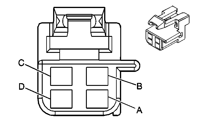
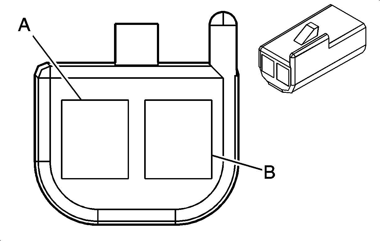
Connector Part Information |
| ||||||
Pin | Wire Color | Circuit No. | Function | ||||
A | DK GRN | 734 | Inside Air Temperature Sensor Signal | ||||
B | BRN | 141 | Ignition Positive Voltage | ||||
C | BLK | 450 | Ground | ||||
D | YEL | 61 | Inside Air Temperature Sensor Return | ||||
| |||||||
|---|---|---|---|---|---|---|---|
Connector Part Information |
| ||||||
Pin | Wire Color | Circuit No. | Function | ||||
A | BLK | 516 | LH A/C Temperature Sensor Signal | ||||
B | YEL | 61 | LH A/C Temperature Sensor Return | ||||

| |||||||
|---|---|---|---|---|---|---|---|
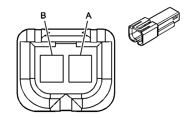
Connector Part Information |
| ||||||
Pin | Wire Color | Circuit No. | Function | ||||
A | BLK | 518 | LH Inside Air Temperature Sensor Signal | ||||
B | YEL/BLK | 61 | LH Inside Air Temperature Sensor Return | ||||
| |||||||
|---|---|---|---|---|---|---|---|
Connector Part Information |
| ||||||
Pin | Wire Color | Circuit No. | Function | ||||
A | LT BLU/BLK | 590 | LH Sun Load Sensor Signal | ||||
B | YEL | 61 | LH Sun Load Sensor Return | ||||

| |||||||
|---|---|---|---|---|---|---|---|
Connector Part Information |
| ||||||
Pin | Wire Color | Circuit No. | Function | ||||
5 | BRN | 141 | Ignition Positive Voltage | ||||
6 | YEL | 1318 | Mode Valve Motor Feed-Lower | ||||
7 | YEL | 1791 | Air Temperature Valve Motor Return | ||||
8 | -- | -- | Not Used | ||||
9 | YEL/BLK | 1814 | Mode Valve Position Sensor Signal - Lower | ||||
10 | GRY | 705 | 5 Volt Reference | ||||

| |||||||
|---|---|---|---|---|---|---|---|
Connector Part Information |
| ||||||
Pin | Wire Color | Circuit No. | Function | ||||
5 | BRN | 141 | Ignition Positive Voltage (B+) | ||||
6 | WHT/BLK | 1236 | Air Temperature Valve Motor Feed - Passenger | ||||
7 | YEL | 1791 | Air Temperature Valve Motor Return | ||||
8 | -- | -- | Not Used | ||||
9 | DK BLU | 1646 | Air Temperature Valve Position Sensor Signal - Passenger | ||||
10 | GRY | 705 | Reference Voltage Feed - 5 Volt Reference | ||||

| |||||||
|---|---|---|---|---|---|---|---|
Connector Part Information |
| ||||||
Pin | Wire Color | Circuit No. | Function | ||||
A | TAN | 517 | RH A/C Temperature Sensor Signal | ||||
B | YEL | 61 | RH A/C Temperature Sensor Return | ||||

| |||||||
|---|---|---|---|---|---|---|---|
Connector Part Information |
| ||||||
Pin | Wire Color | Circuit No. | Function | ||||
A | BLK/WHT | 520 | RH Inside Air Temperature Sensor SIgnal | ||||
B | YEL/BLK | 61 | RH Inside Air Temperature Sensor Return | ||||

| |||||||
|---|---|---|---|---|---|---|---|
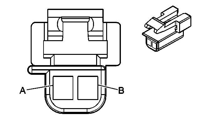
Connector Part Information |
| ||||||
Pin | Wire Color | Circuit No. | Function | ||||
A | GRY | 1548 | RH Sun Load Sensor Signal | ||||
B | YEL | 61 | RH Sun Load Sensor Return | ||||
| |||||||
|---|---|---|---|---|---|---|---|
Connector Part Information |
| ||||||
Pin | Wire Color | Circuit No. | Function | ||||
A | YEL | 1172 | Auxiliary Blower Motor Feed | ||||
B | ORN | 1052 | Auxiliary Blower Motor Output | ||||

| |||||||
|---|---|---|---|---|---|---|---|
Connector Part Information |
| ||||||
Pin | Wire Color | Circuit No. | Function | ||||
A | LT BLU | 72 | Blower Switch Output-Medium 2 | ||||
B | PPL | 73 | Blower Switch Output-Medium 3 | ||||
C | ORN | 1052 | Auxiliary Blower Output | ||||
D | WHT | 63 | Blower Switch Output-Medium 1 | ||||
| |||||||
|---|---|---|---|---|---|---|---|
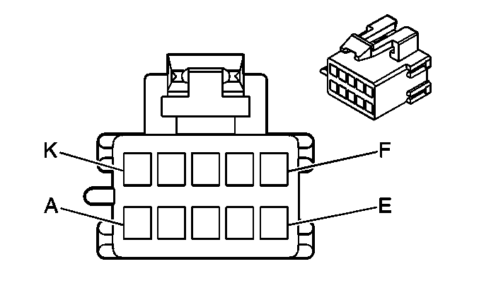
Connector Part Information |
| ||||||
Pin | Wire Color | Circuit No. | Function | ||||
A | BLK | 350 | Ground | ||||
B | BRN | 141 | Ignition Positive Voltage | ||||
C | -- | -- | Not Used | ||||
D | YEL | 1491 | Dash Integration Module Output- Backlighting Lamps (LH Drive) | ||||
D | YEL/BLK | 1491 | Dash Integration Module Output- Backlighting Lamps (RH Drive) | ||||
E | BLK | 350 | Ground | ||||
F | TAN | 63 | Blower Switch Output-Medium 1 | ||||
G | LT BLU | 72 | Blower Switch Output-Medium 2 | ||||
H | PPL | 73 | Blower Switch Output-Medium 3 | ||||
J | ORN | 1052 | Auxiliary Blower Motor Circuit | ||||
K | PNK | 1593 | Diverter Motor Feed | ||||

| |||||||
|---|---|---|---|---|---|---|---|
Connector Part Information |
| ||||||
Pin | Wire Color | Circuit No. | Function | ||||
5-6 | -- | -- | Not Used | ||||
7 | BLK | 350 | Ground | ||||
8 | PNK | 1593 | Diverter Motor Feed | ||||
9 | -- | -- | Not Used | ||||
10 | BRN | 141 | Ignition Positive Voltage | ||||
