For 1990-2009 cars only
Lumbar Component Replacement - Power Module Replacement (AL2)
Removal Procedure
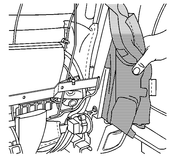
- Remove the seat back trim cover. Refer to Front Seat Back Trim Replacement .
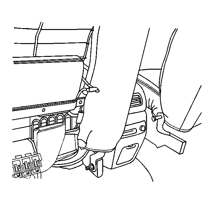
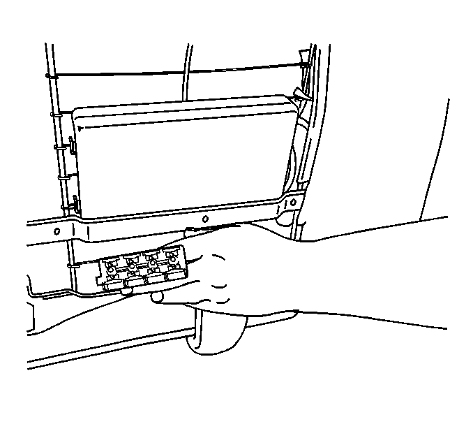
- Disconnect electrical connection from the module.
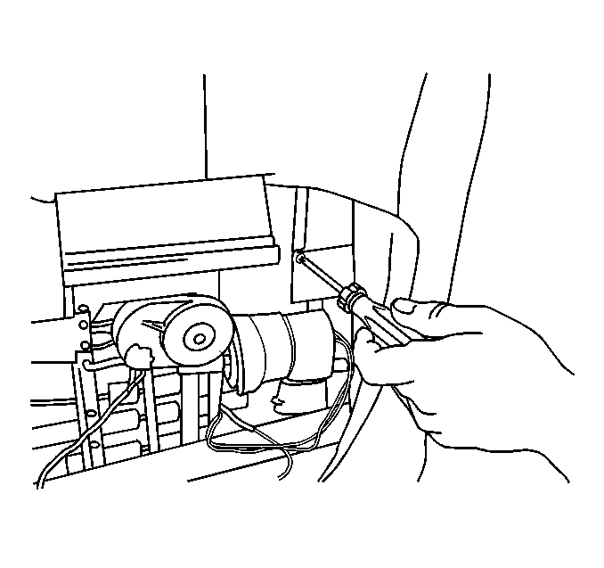
- Drill out the rivets retaining module to the bracket.

Installation Procedure
- Install module to the bracket with self-tapping fasteners or rivets.
- Connect the electrical connector.
- Install the seat back trim cover. Refer to Front Seat Back Trim Replacement .

Lumbar Component Replacement - Power Motor Replacement (AC9)
Removal Procedure
- Remove the seat back trim cover. Refer to Front Seat Back Trim Replacement .
- Remove the seat cover J channels from the seat back frame as necessary to access motor.
- Remove the electrical connector and air line from the pump motor assembly.
- Remove the hog rings retaining bag and motor assembly to the wire seat back frame.
- Remove the bag and motor assembly.

Installation Procedure
- Secure bag and pump motor assembly to the seat back frame with hog rings.
- Connect the pump motor electrical connector and air line.
- Install the seat cover J channels to seat back frame.
- Install the seat back trim cover. Refer to Front Seat Back Trim Replacement .


Lumbar Component Replacement - Power Lumbar Module (AC9)
Removal Procedure
- Adjust the seat forward and up.
- Remove the seat back trim cover. Refer to Front Seat Back Trim Replacement .
- Disconnect both air line connectors from the lumbar module.
- Remove the seat cover J channels from the seat frame as necessary to access module wiring.
- Release the wire retainers on the main module wiring harness.
- Disconnect the main module wiring harness electrical connector from under the seat and gently pull the harness through seat frame.
- Disconnect the electrical connector and single air line coming from the pump motor to the adaptive lumbar module.
- Cut the straps retaining the adaptive lumbar module to the wire seat back frame.
- Unclip the lumbar module from wire seat back frame.
- Remove the lumbar module.


Installation Procedure
- Clip the lumbar module on seat back wire frame.
- Secure the lumbar module wire seat back frame with straps.
- Connect the single air line and electrical connector into pump motor to lumbar module.
- Route the main wiring harness through seat back wire frame to underside of seat.
- Install the wiring harness retainers and reconnect electrical connector (under seat frame).
- Install the seat back J channels onto the seat back frame.
- Connect both air line connectors onto the adaptive lumbar module.
- Operate recliner assembly forward and back while checking for interference with the module wiring and air line connections.
- Install the seat back trim cover. Refer to Front Seat Back Trim Replacement .


Lumbar Component Replacement - Power Lumbar Replacement (AL2)
The lumbar assembly is part of the seat back frame, and cannot be serviced separately. If the lumbar assembly requires service, the seat back frame must be replaced. Refer to Front Seat Back Frame Replacement .
