Caution: Failure to adhere to the following precautions before tire balancing
can result in personal injury or damage to components:
• Clean away any dirt or deposits from the inside of the wheels. • Remove any stones from the tread. • Wear eye protection. • Use coated weights on aluminum wheels.
Important: The tires can be balanced either on-vehicle or off-vehicle, but the off-vehicle balancing procedures are recommended. Off-vehicle methods are better because tire rotation will not affect the balancing. The off-vehicle balancers are also more accurate than the on-vehicle balancers. Off-vehicle balancers can perform dynamic balancing as well as static balancing.

Tire and wheel balancers can drift out of calibration without warning, or can become inaccurate as a result of abuse. The balancer calibration should be inspected every two weeks, and whenever the readings are questionable.
Tire Balancer Calibration Test
- Spin the balancer without a wheel or any of the adapters on the shaft.
- Inspect the balancer readings.
- Balance a tire and wheel assembly that is within radial and lateral tolerances to ZERO.
- Add a 3 ounce test weight to the wheel at any location.
- Spin the tire and wheel assembly again, noting the readings.
- With the assembly unbalanced to 3 ounces, cycle the balancer 5 times.
- Take the balancer readings:
- Index the tire and wheel assembly at four separate locations on the balancer shaft, 90 degrees apart.
- Cycle the balancer with the assembly at each location.
- Take the balancer readings:
Specification
0.00-0.25 oz
| • | In the static and dynamic modes, the balancer should call for 3 ounces of weight, 180 degrees opposite the test weight. |
| • | In the dynamic mode only, the weight should be called for on the flange of the wheel opposite the last weight. |
Specification
Variation: 0.25 oz or less
Specification
Variation: 0.25 oz or less
Tire Balancing Guidelines
There are two methods used to balance tire and wheel assemblies:
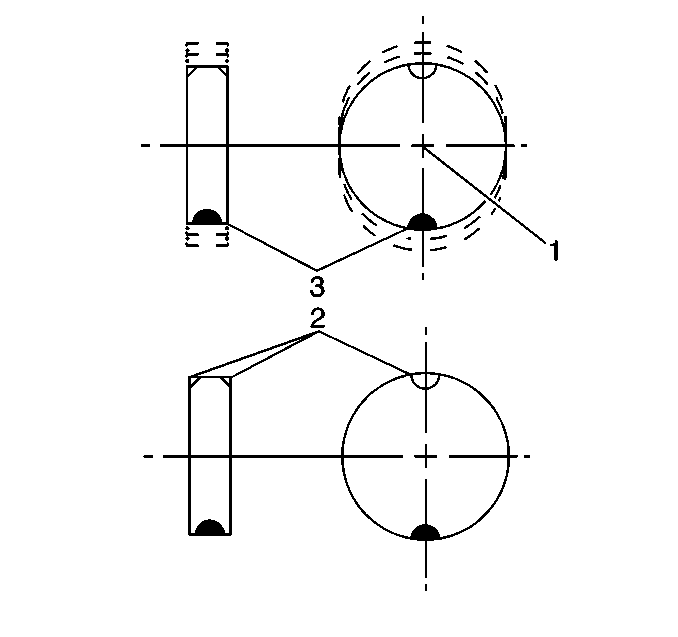
| • | Static balance is the equal distribution of weight around the wheel. The wheel balance weights (2) are positioned on the wheel in order to offset the effects of the heavy spot (3). Wheels that are statically unbalanced produce a bouncing action called tramp. |
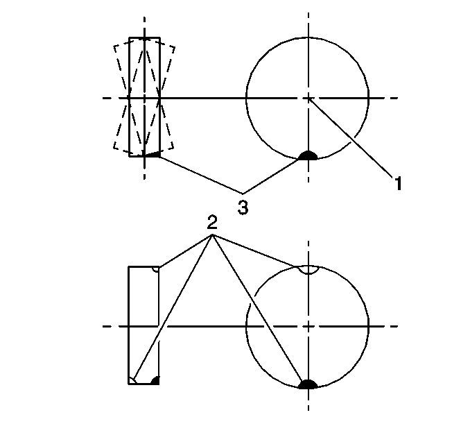
| • | Dynamic balance is the equal distribution of weight on each side of the spindle centerline (1). The wheel balance weights (2) are positioned on the wheel in order to offset the effects of the heavy spot (3). When the tire spins, the equal distribution of weight eliminates the tendency for the wheel to move from side to side. Wheels that are dynamically unbalanced may cause shimmy. |
Most off-vehicle balancers are capable of checking both types of balance simultaneously.
As a general rule, most vehicles are more sensitive to static imbalance than to dynamic imbalance, with as little as 0.50-0.75 oz capable of inducing a vibration in some vehicles.
| • | Balance all four tires as close to ZERO as possible. |
| • | Carefully follow the wheel balancer manufacturer's instructions for proper mounting techniques to be used on different types of wheels. |
| • | Regard aftermarket wheels, especially those incorporating universal lug patterns, as potential sources of runout and mounting problems. |
| • | Use the correct coated weights on aluminum wheels. |
| • | Recheck the tire and wheel assemblies for excessive runout after they have been corrected and installed. |
| • | Evaluate the vehicle at the complaint speed and note if the vibration has been corrected. |
| • | If the vibration is still present, or is reduced but still unacceptable, you may find one of two possibilities: |
| - | On-vehicle imbalance |
| - | Radial or lateral force variation |
Correcting On-Vehicle Imbalance
On-vehicle imbalance may result from components other than the tire and wheel assemblies having imbalance. An on-vehicle high-speed balance or replacement of suspected components may be necessary in order to correct the condition.
Rotors do not have a set tolerance. However, rotors with more than 0.75 ounce imbalance have the potential to cause vibration. The rotors can be inspected for imbalance using either the on-vehicle or the off-vehicle method as described below:
Checking Rotor Imbalance (On-Vehicle)
- Support the vehicle rear axle on a suitable hoist. Refer to Lifting and Jacking the Vehicle in General Information.
- Remove the rear tire and wheel assemblies.
- Reinstall the wheel nuts in order to retain the rotors.
- Take the necessary precautions. Refer to
Caution: One or more of the following guidelines may apply when performing specific required tests in the work stall:
in General Information.• When a test requires spinning the drive wheels with the vehicle jacked up, adhere to the following precautions: - Do not exceed 56 km/h (35 mph) when spinning one drive wheel with the other drive wheel stopped. This limit is necessary because the speedometer indicates only one-half the actual vehicle speed under these conditions. Personal injury may result from excessive wheel spinning. - If all of the drive wheels are spinning at the same speed, do not exceed 112 km/h (70 mph). Personal injury may result from excessive wheel spinning. - All persons should stay clear of the rotating components and the balance weight areas in order to avoid possible personal injury. - When running an engine in the repair stall for an extended period of time, use care not to overheat the engine and the transmission. • When a test requires jacking up the vehicle and running with the wheels and brake rotors removed, adhere to the following precautions: - Support the suspension at normal ride height. - Do not apply the brake with the brake rotors removed. - Do not place the transmission in PARK with the drive axles spinning. - Turn Off the ignition in order to stop the powertrain components from spinning. • When running an engine in the work stall, use the exhaust removal system to prevent breathing dangerous gases. - Run the vehicle at the complaint speed while inspecting for vibration.
- If the vibration still exists, perform the following steps:
- If the vibration is eliminated, perform the following steps:
| 6.1. | Remove the rotors. |
| 6.2. | Run the vehicle back to speed. |
| 7.1. | Reinstall the rotors one at a time. |
| 7.2. | Perform the vibration test for each rotor. |
| 7.3. | Replace the rotor causing the imbalance. |
| 7.4. | Inspect the balance of the new rotor. |
Checking Rotor Imbalance (Off-Vehicle)
- Measure the diameter and the width of the rotor.
- Mount the rotor on a balancer in the same manner as a wheel.
- Inspect for static imbalance.
Important: The rotors can only be inspected for static imbalance. Ignore the dynamic imbalance reading.
On-Vehicle Balancing Procedure
The vibration problem may not be correctable with the components removed from the vehicle. An on-vehicle high-speed balancer may be required in order to balance the tire and wheel assemblies while still mounted on the vehicle. On-vehicle balancing will balance the hubs and the rotors simultaneously, and will compensate for any residual runout encountered as a result of mounting the tire and wheel assemblies on the vehicle as opposed to off-vehicle balancing.
Follow the on-vehicle balancer manufacturer operator's manual for specific instructions while keeping the following tips in mind:
Balancing Tips
| • | Do not remove the off-vehicle balancing weights. The purpose of on-vehicle balance is to FINE TUNE the assembly balance already achieved, not to start over again. |
| • | If the on-vehicle balance calls for more than 1 ounce of additional weight, split the weight between the inboard and outboard flanges of the wheel, so as not to upset the dynamic balance of the assembly that was achieved in the off-vehicle balance. |
| • | An EVA vibration sensor placed on the fender of the vehicle during the on-vehicle balance is an excellent indicator of the amplitude of the vibration, and the effect that the balance has on the vibration. |
| • | Evaluate the vibration after the on-vehicle balance in order to determine if the vibration condition has been resolved. |
Radial Force Variation
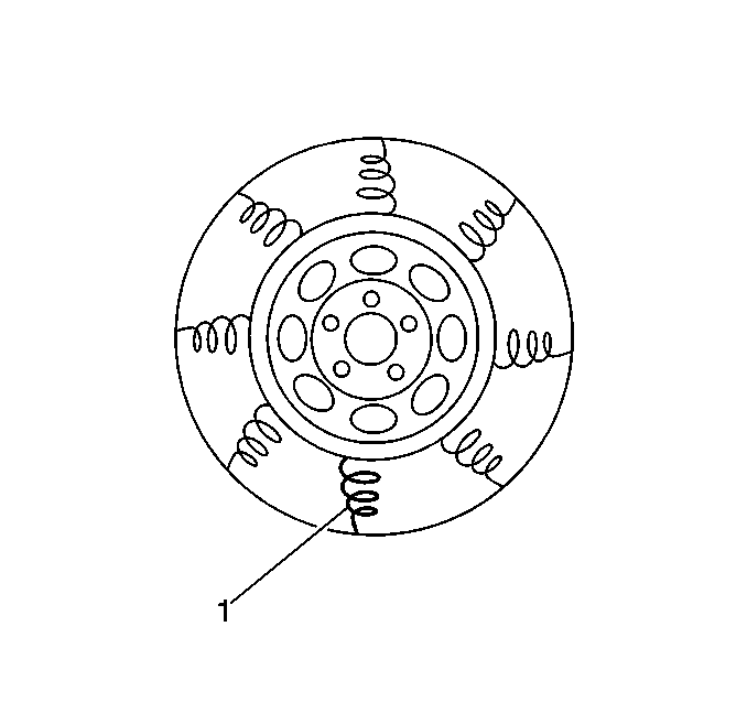
Radial force variation is the difference in the stiffness of a tire as the tire rotates and contacts the road. The tire and wheel assemblies have some variation due to splices in the tire plies. These splices do not cause a problem unless the force variation is excessive. These STIFF SPOTS in the tire (1) can deflect the tire and wheel assembly upward as the assembly contacts the road.
If the tire has only one stiff spot, the spot will deflect the spindle once per each revolution of the tire and wheel assembly, thus causing a first-order tire/wheel vibration. If the tire has two stiff spots, the spots cause a second-order vibration. First- and second-order tire/wheel vibrations are the most common to occur as a result of radial force variation. Third-, fourth-, or higher orders are possible but rarely occur.
The most effective way to minimize the possibility of force variation as a factor in tire and wheel assembly vibrations is to ensure that the tire and wheel assembly runout is at an absolute minimum. However, some tire and wheel assemblies exhibit vibration-causing force variation even though they are within runout and balance tolerances. These instances are becoming rare due to tighter tolerances and higher standards in manufacturing.
The following two alternatives are available if force variation is suspected as a factor in tire and wheel assembly vibration complaints:
| • | Buff the tires. |
| • | Substitute one or more known good tire and wheel assemblies. |
The tires may be buffed on a tire matching machine that is designed to remove small amounts of rubber from the outer rows of the tread blocks at the location of the stiff spots under load. This eliminates the spindle deflection. This type of equipment is not currently in widespread use. Do not use a TRUER or any tool that is designed to make the tire perfectly round. These tools will not correct the condition.
You may substitute one or more known good tire and wheel assemblies when a tire manufacturer is not available locally.
Lateral Force Variation
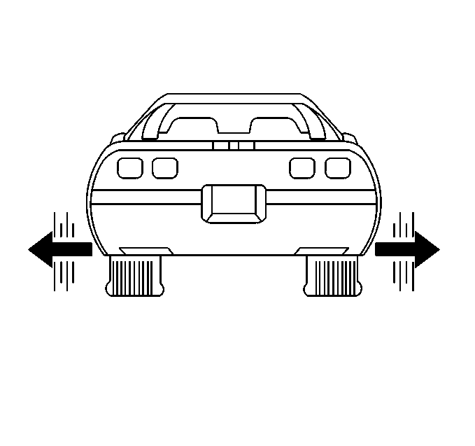
Lateral force variation tends to deflect the vehicle sideway, or laterally. Lateral force variation is based on the same concept as radial force variation. A SNAKY belt inside the tire may be the cause of lateral force. The tire substitution method may have to be used before tire replacement.
A lateral force variation condition is rare. The best way to eliminate lateral force variation as a factor in tire and wheel vibration conditions is to ensure that the lateral runout of the tire and wheel assemblies is at an absolute minimum.
The vehicle will WOBBLE or WADDLE at slow speeds of 8-40 km/h (5-25 mph) when lateral force variation is excessive. This condition is usually related to the first-order of tire and wheel rotation.
Wheel Hub/Axle Flange Runout
Inspect the wheel hub/axle flange runout when lateral runout occurs during on-vehicle testing but not during off-vehicle testing. The tolerances provided are only guidelines. Perform corrections only if the on-vehicle runout cannot be brought to within tolerance.
- Position the dial indicator on the machined surface of the hub, the axle flange, or the rotor, outside of the wheel studs.
- Rotate the hub in order to find the low spot.
- Set the dial indicator to zero at the low spot.
- Rotate the hub again and check the total amount of runout.
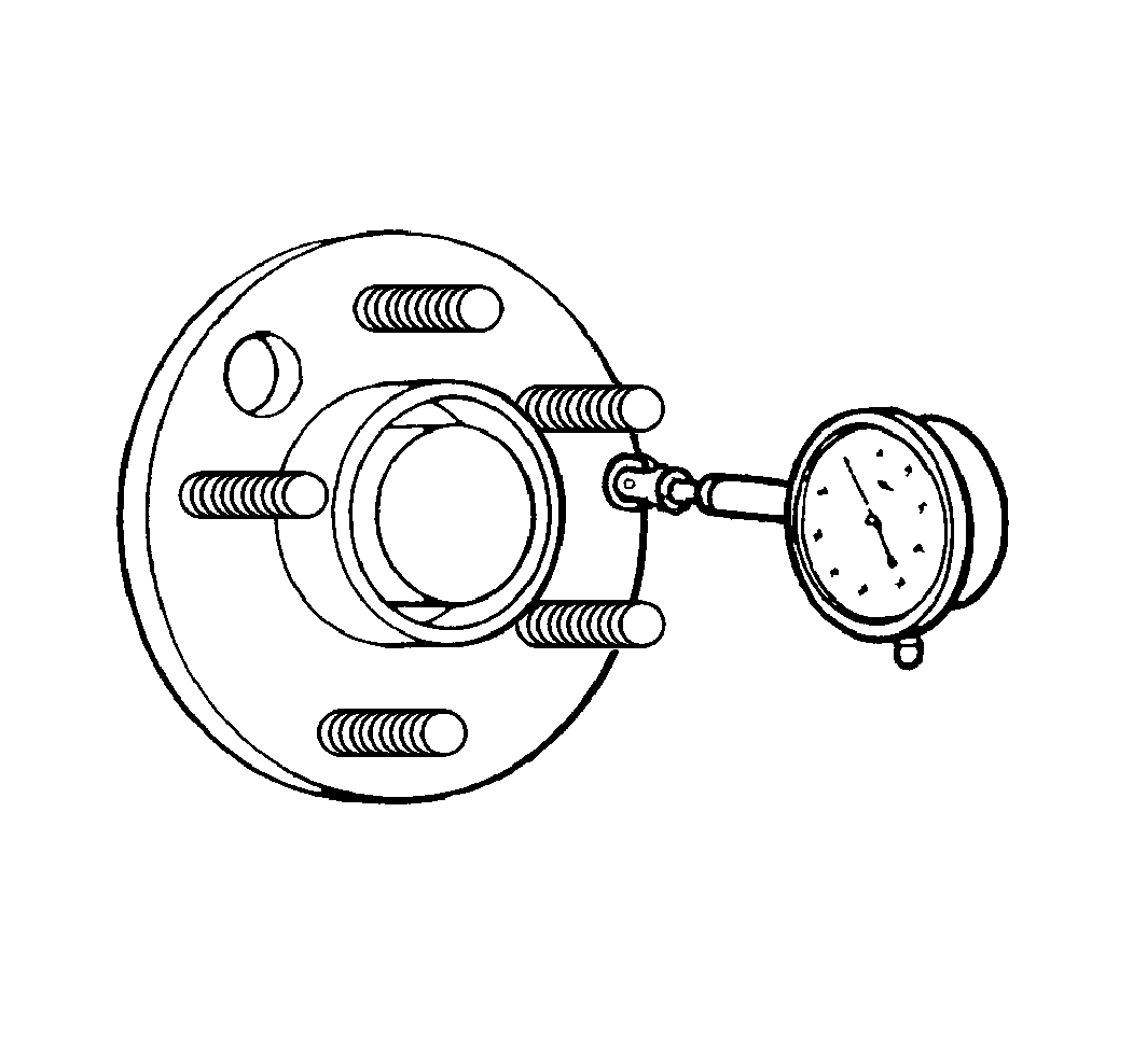
Specification (Guideline)
Runout tolerance: 0.127 mm (0.005 in)
Wheel Stud (Stud Circle) Runout
Use the following procedure whenever the off-vehicle radial runout and the on-vehicle radial runout are significantly different, and earlier attempts to correct the tire and wheel vibration condition have not been successful.
- Position the dial indicator in order to contact the wheel mounting studs.
- Turn the hub to register on each of the studs.
- Zero the dial indicator on the lowest stud.
- Rotate the hub again and check the total amount of runout.
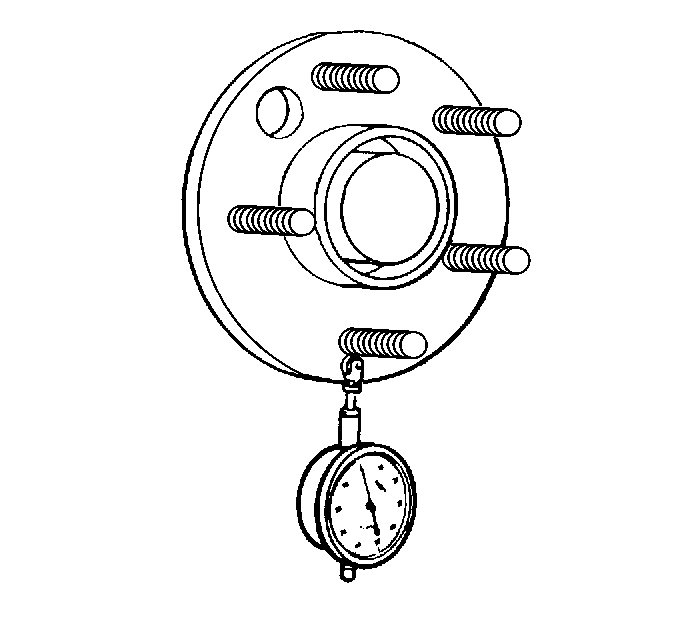
Measure the stud runout as close to the flange as possible.
Specification (Guideline)
Runout tolerance: 0.254 mm (0.010 in)
