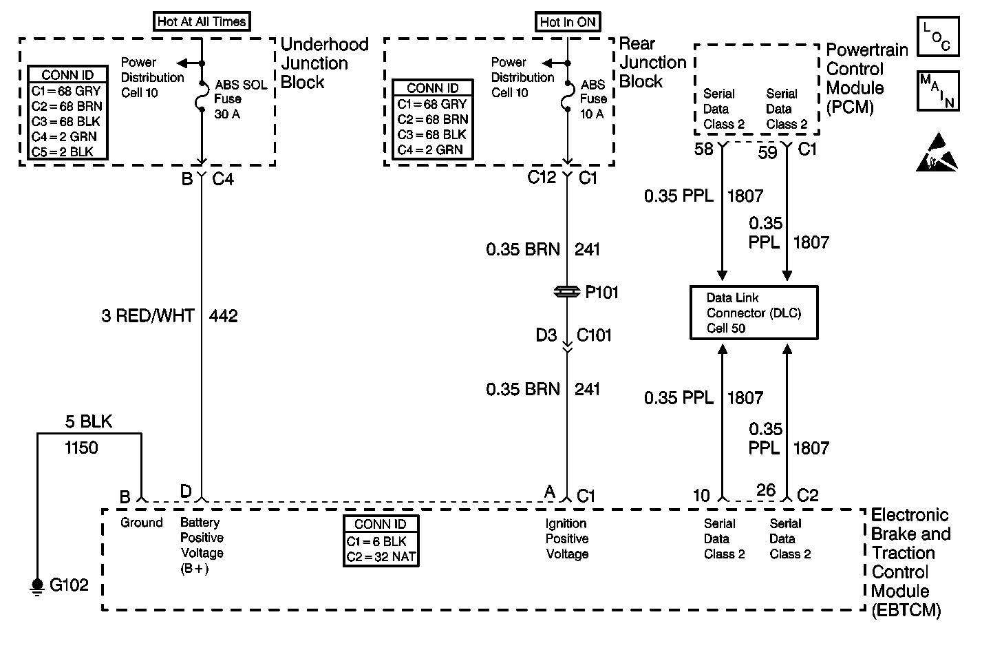
Circuit Description
The class 2 serial data line allows all of the modules on the line to transmit information to each other as needed. Each module is assigned an ID. All of the information sent out on the line is assigned a priority by which it is received. When the ignition is turned ON, each module begins to send and receive information. Each module on the class 2 serial data line knows what information the module needs to send out and what information the module should be receiving. What the modules do not know is which module is supposed to send the information. This information is only learned after the module has received the information needed along with the ID of the module that sent the information. This information is then remembered until the ignition switch is turned off.
Conditions for Setting the DTC
| • | The ignition is ON. |
| • | The PCM does not receive any messages from the EBTCM for 7 seconds. |
Action Taken When the DTC Sets
| • | A malfunction DTC is stored. |
| • | The TCS is disabled. |
| • | The TRACTION CONTROL indicator is turned ON. |
| • | The ABS remains functional. |
Conditions for Clearing the DTC
| • | The condition for DTC is no longer present and you used scan tool Clear DTCs function. |
| • | The condition for DTC is no longer present and you used the On-Board Clear DTCs function. |
| • | The EBTCM does not detect the DTC in 50 drive cycles. |
Diagnostic Aids
| • | It is very important that a thorough inspection of the wiring and connectors be performed. Failure to carefully and fully inspect wiring and connectors may result in misdiagnosis, causing part replacement with reappearance of the malfunction. |
| • | An intermittent malfunction can be caused by poor connections, broken insulation, or a wire that is broken inside the insulation. |
| • | If an intermittent malfunction exists, refer to Intermittents and Poor Connections Diagnosis in Wiring Systems. |
Test Description
The numbers below refer to step numbers on the diagnostic table.
-
Checks to see if the dash integration module (DIM) is sending the proper power mode position message.
-
Checks to see if the EBTCM is sending out the required information via serial data class 2.
Step | Action | Value(s) | Yes | No | ||||||||
|---|---|---|---|---|---|---|---|---|---|---|---|---|
1 | Did you perform the Diagnostic System Check? | -- | Go to Step 2 | Go to Diagnostic System Check | ||||||||
2 | Check the following grounds, making sure each ground is clean and torqued to the proper specifications:
Were any loose, damaged, or corroded grounds found? | -- | Go to Step 3 | Go to Step 4 | ||||||||
3 | Repair the ground as necessary. Refer to Wiring Repairs in Wiring Systems. Did you complete the repair? | -- | Go to Diagnostic System Check | -- | ||||||||
4 |
Are DTCs U1016, U1255, U1300, or U1301 set as history DTCs? | -- | Go to Step 5 | |||||||||
Did the scan tool indicate the proper position for each power mode position? | -- | Go to Step 6 | Go to Diagnostic System Check - Body Control System in Body Control System | |||||||||
Using the scan tool in the Applications menu, read the Class 2 Normal Mode Message Monitor. Is the EBTCM sending a Class 2 Normal Mode Message? | -- | Go to Step 7 | Go to Step 8 | |||||||||
7 | Suspect PCM. Refer to Powertrain On Board Diagnostic (OBD) System Check in Engine Controls - 4.6L. Is the PCM diagnosis complete? | -- | Go to Diagnostic System Check | -- | ||||||||
8 | Replace the EBTCM. Refer to Electronic Brake Control Module Replacement . Did you complete the repair? | -- | Go to Diagnostic System Check | -- |
