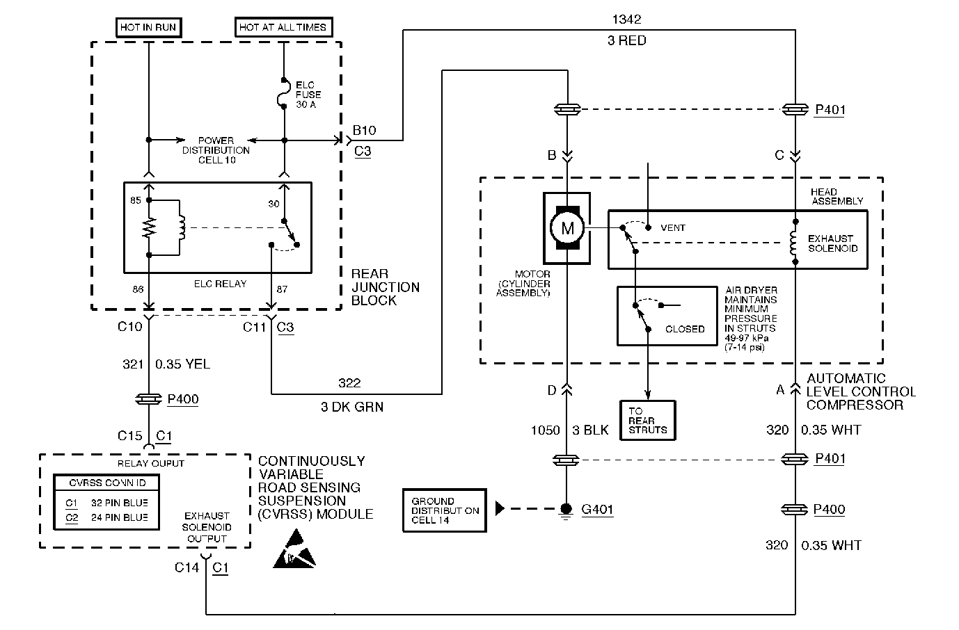
Circuit Description

The compressor is switched ON and OFF via an ELC compressor relay which is controlled by the CVRSS module. The control module circuitry provides a switched path to ground (low-side drive) whenever compressor activity is required. This drive circuit is also continually monitored to determine if the voltage level agrees with the commanded state.
Conditions for Setting the DTC
The DTC is set when the CVRSS module sees a low voltage condition at pin C15 during a compressor OFF-state.
The DTC will turn HISTORY when the CVRSS module no longer senses a low voltage condition at pin C15 while the ELC compressor relay output drive is in an OFF-state.
Action Taken When the DTC Sets
The ELC compressor relay output drive is disabled for the remainder of the ignition cycle.
Conditions for Clearing the MIL/DTC
| • | Use the scan tool. |
| • | Refer to the CLEAR RSS CODES feature. |
Diagnostic Aids
This fault condition is detectable only when the ELC compressor relay output is commanded to the OFF state, which occurs whenever compressor activity is not required. The control module expects to see a high voltage condition during the OFF-state.
Only electrical problems with the ELC compressor relay coil circuit are flagged. Compressor motor problems and pneumatic leakage problems do not set a DTC, but the CVRSS module shuts the ELC compressor relay off if there is no progress, or if excessive run times occur. Recovery is not attempted until the ignition is cycled OFF and ON.
Test Description
Important:
• Do not backprobe the sensors, actuators, or any sealed connectors. • When all the diagnostics and repairs are complete, clear the DTCs
and verify the operation.
The number(s) below refer to the step number(s) on the diagnostic table.
-
This step checks to see if the ignition fuse to the relay is blown.
-
This step checks to see if ignition voltage is present and checks for an internal open circuit condition in the relay coil.
-
This step checks for an open circuit condition or short circuit to ground condition in circuit 321.
-
This step checks for an open circuit condition in the juction block.
Step | Action | Value(s) | Yes | No |
|---|---|---|---|---|
1 | Was the Road Sensing Suspension Diagnostic System Check performed? | -- | Go to Step 2 | |
2 |
Is the voltage above the specified value? | 10 V | Go to Step 10 | Go to Step 3 |
3 |
Is the voltage above the specified value? | 10 V | Go to Step 8 | Go to Step 4 |
4 |
Is the resistance the specified value? | OL | Go to Step 5 | Go to Step 6 |
5 | Measure the resistance between CVRSS module connector C1, terminal C15, and Rear Junction Block connector C3, terminal C10. Is the resistance equal to or below the specified value? | 5 ohms | Go to Step 9 | Go to Step 7 |
6 | Repair the short circuit to ground in CKT 321. Is the repair complete? | -- | -- | |
7 | Repair the open circuit condition in circuit 321. Is the repair complete? | -- | -- | |
8 | Replace the ELC relay. Is the replacement complete? | -- | -- | |
9 | Replace the Rear Junction Block. Is the replacement complete? | -- | -- | |
10 |
Refer to Intermittents and Poor Connections . Is DTC C1736 set? | -- | Go to Step 11 | |
11 |
Important: The controller must be calibrated. Is the CVRSS control module calibrated? | -- | -- |
