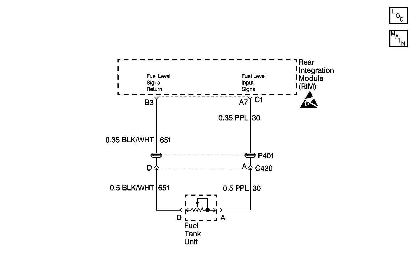
Circuit Description
When the ignition switch is in RUN, the Rear Integration Module (RIM) reads fuel level directly across terminals A7 and B3 on RIM connector C1. These terminals are wired to the fuel level sensor on CKT 30 (PPL) and CKT 651 (BLK). The fuel level sensor has a resistance range from 40 ohms (below E) to 250 ohms (above F). The RIM filters the raw fuel level data and transmits the fuel data in its filtered state to the Instrument Panel Cluster (IPC) via Class 2 serial data line. The RIM sends the IPC this filtered fuel at each change of 0.5 liters. The IPC uses the fuel data received from the RIM to determine the proper fuel gauge pointer position.
Conditions for Setting the DTC
| • | DTC B0530 only sets if B1328 or B1327 is not current in RIM memory. |
| • | DTC B0530 sets if the RIM determines that the fuel sensor is stuck. The RIM sets this DTC if the fuel sensor feedback (across RIM connector C1 terminals A7 and B3) does not fluctuate at least 5 ohms during the last 50 miles (80 km). The RIM keeps track of the mileage without resetting at power off conditions. The RIM resets the mileage for this DTC calculation when the RIM detects a sensor resistance change of 5.0 ohms. |
Action Taken When the DTC Sets
| • | DTC B0530 is stored in RIM memory. |
| • | The RIM sends a Class 2 message to the PCM that this condition exists. The message includes the fuel level equivalent of this resistance value. |
| • | The IPC drives the fuel gage pointer to E. |
| • | The Driver Information Center (DIC) displays the SERVICE FUEL SYSTEM message. |
Conditions for Clearing the DTC
| • | DTC B0533 clears (status changes from current to history) when the RIM no longer detects the conditions which caused the DTC to set. |
| • | A history DTC clears after 50 consecutive ignition cycles if the condition for the malfunction is no longer present. |
| • | Current and history DTCs may be cleared using a scan tool or using the IPC on-board clearing DTCs feature. |
Diagnostic Aids
Refer to Fuel Gauge Inaccurate for additional diagnosis of the fuel gauge.
Test Description
The numbers below refer to the step numbers on the diagnostic table:
-
Perform the Body Control Module Diagnostic System Check before continuing with the diagnosis of this DTC.
-
Clear all DTCs and cycle ignition to check that the DTC did not erroneously set.
-
Clear all DTCs after the repair procedure is complete.
Step | Action | Value(s) | Yes | No |
|---|---|---|---|---|
Was the Body Control Module Diagnostic System Check performed? | -- | |||
2 | Is DTC B0532 also current? | -- | ||
3 | Is DTC B0533 also current? | -- | ||
Does the fuel gauge go to empty? | -- | Go to Fuel Gage Inaccurate or Inoperative in Instrument Panel,Gauges and Console | ||
5 | Replace fuel level sensor. Refer to Fuel Level Sensor Replacement. Is replacement complete? | -- | -- | |
Are all DTCs cleared? | -- | -- |
