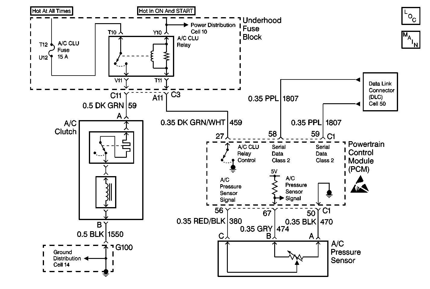
Circuit Description
The A/C pressure sensor is a located in the high pressure side of the A/C system. The A/C pressure sensor is used by the Powertrain Control Module (PCM) and the Dash Integration Module (DIM) to monitor A/C pressure. The DIM uses this information to command ON the engine cooling fans when the A/C pressure is high and to keep the compressor disengaged when the A/C pressure is excessively high.
The PCM applies a 5.0 volt reference and a sensor ground. Changes in the A/C pressure will cause the A/C pressure signal input to the PCM to vary. The PCM monitors the A/C refrigerant pressure circuit and can determine when the signal is out of range of the sensor. When the signal is out of range for a period of time the PCM will set a DTC. The DIM will set DTC B1324. When the A/C pressure is high, above 2964 kPa (430 psi) the A/C compressor clutch will not engage.
Conditions for Setting the DTC
| • | The engine is running. |
| • | A/C is requested. |
| • | The A/C pressure is greater then 2964 kPa (430 psi). |
Action Taken When the DTC Sets
| • | The PCM will not illuminate the Malfunction Indicator Lamp (MIL). |
| • | The A/C compressor clutch will not engage. |
Conditions for Clearing the MIL/DTC
| • | Using a scan tool. |
| • | A history DTC will clear after 40 consecutive warm-up cycles have occurred without a malfunction. |
| • | A current DTC will clear when the diagnostic runs and does not fail. |
| • | The battery voltage for the DIM is interrupted. |
| • | A/C pressure drops below 1386 kPa (201 psi). |
Diagnostic Aids
Check the following conditions:
| • | A malfunction within the refrigerant system causing high pressure. |
| • | Poor connection at the PCM. |
| • | Damaged harness. Inspect the wiring harness for damage. |
| • | If the harness appears to be OK, observe the A/C pressure display on the scan tool while moving connectors and wiring harnesses related to the A/C pressure sensor. A change in the A/C pressure display will indicate the location of the malfunction. |
Test Description
The numbers below refer to the step numbers on the diagnostic table.
-
This step determines whether the Body Control Module (BCM) Diagnostic System Check was performed.
-
This step determines if the scan tool pressure reading is accurate.
-
This step determines if the sensor is operating.
-
This step clears all of the DTCs after the repair procedures are complete.
Step | Action | Value(s) | Yes | No |
|---|---|---|---|---|
Was the BCM diagnostic system check performed? | -- | Go to Step 2 | ||
2 |
Is the A/C pressure status high? | -- | Go to Step 3 | |
Are the pressures displayed on the scan tool and the pressures displayed on the J 39183-C within 69 kPa (10 psi) of each other? | -- | Go to Cooling Insufficient - Air Conditioning (A/C) Inoperative in HVAC Systems with A/C-Automatic | Go to Step 4 | |
Does the pressure status change? | -- | Go to Step 5 | Go to Step 6 | |
5 |
Is the repair complete? | -- | Go to Step 7 | -- |
6 |
Is the repair complete? | -- | Go to Step 7 | -- |
Is the A/C system operating correctly? | -- | -- |
