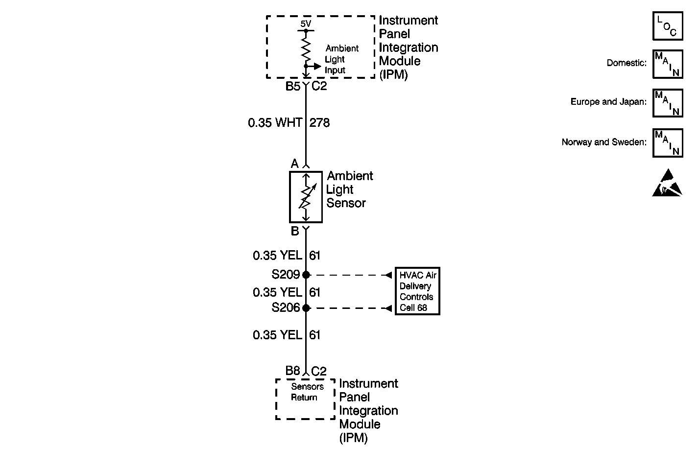
Circuit Description
The instrument panel integration module (IPM) receives an input from the ambient light sensor. The IPM supplies the ground for the sensor through the sensor return. The resistance of the ambient light sensor varies as the outside light changes. When the resistance of the ambient light sensor is less than 23 Kohms for bright light. It is greater than 31 Kohms for complete darkness. As the resistance of the ambient light sensor varies, the voltage input to the IPM changes. The IPM determines whether it is light or dark outside. The IPM then sends a message via the class 2 serial data line to the dash integration module (DIM) and the rear integration module (RIM) indicating whether it is light or dark outside.
Conditions for Setting the DTC
The IPM will set the DTC B2419 any time it detects that the ambient sensor input voltage is out of range.
Specification
Normal sensor input voltage: 0.095-4.75 V
Action Taken When the DTC Sets
The IPM will assume that the ambient light level indicates darkness for all functions needing the outside light status.
Conditions for Clearing the DTC
| • | The IPM sees that the ambient light sensor input voltage is within the valid range. |
| • | Use the On-Boards clearing DTCs feature. |
| • | Use a scan tool. |
Test Description
The numbers below refer to the step numbers on the diagnostic table:
-
Perform the Body Control Module Diagnostic System Check or Lighting Systems Diagnostic System Check before continuing with the diagnosis of this DTC.
-
Checks if the value that the instrument panel integration module (IPM) is reading from the ambient light sensor is too high.
-
Checks if the value that the instrument panel integration module (IPM) is reading from the ambient light sensor is too low.
-
Checks if the DTC is still set.
-
Checks if the resistance of the ambient light sensor is too high.
-
Checks if the resistance of the ambient light sensor is too low.
-
Clear all DTCs after the repair procedure is complete.
Step | Action | Value(s) | Yes | No |
|---|---|---|---|---|
Was the entire Body Control Module Diagnostic System Check or Lighting Systems Diagnostic System Check performed? | -- | Go to Step 2 | Go to Diagnostic System Check - Body Control System or Diagnostic System Check - Lighting Systems | |
Is the Twilight Photocell value greater than the specified value? | 250 Counts (4.75 Volts) | Go to Step 6 | Go to Step 3 | |
Expose the ambient light sensor to a bright incandescent light. Is the Twilight Photocell value less than the specified value? | 5 Counts (0.095 Volts) | Go to Step 9 | Go to Step 4 | |
Is DTC B2419 set as current? | -- | Go to Step 5 | Go to Diagnostic System Check - Body Control System or Diagnostic System Check - Lighting Systems | |
5 | Replace the instrument panel integration module (IPM). Refer to Body Control Module Replacement in Body Control System. Is the IPM replacement complete? | -- | Go to Step 14 | -- |
Is the resistance greater than the specified value? | 31 Kohms | Go to Step 12 | Go to Step 7 | |
7 |
Is the resistance less than the specified value? | 5 ohms | Go to Step 8 | Go to Step 13 |
8 | Repair the open in CKT 61 (YEL) between S209 and the ambient light sensor. Refer to Wiring Repairs in Wiring Systems. Is the circuit repair complete? | -- | Go to Step 14 | -- |
Is the resistance greater than the specified value? | 23 Kohms | Go to Step 12 | Go to Step 10 | |
10 |
Is the resistance less than the specified value? | 5 ohms | Go to Step 11 | Go to Step 5 |
11 | Repair the short to ground in CKT 278 (WHT). Refer to Wiring Repairs in Wiring Systems. Is the circuit repair complete? | -- | Go to Step 14 | -- |
12 | Replace the ambient light sensor. Refer to Sunload and Twilight Sentinel Sensor Replacement . Is the ambient light sensor replacement complete? | -- | Go to Step 14 | -- |
13 | Repair the open in CKT 278 (WHT) between the IPM and the ambient light sensor. Refer to Wiring Repairs in Wiring Systems. Is the circuit repair complete? | -- | Go to Step 14 | -- |
Are all DTCs cleared? | -- | Go to Diagnostic System Check - Body Control System or Diagnostic System Check - Lighting Systems | -- |
