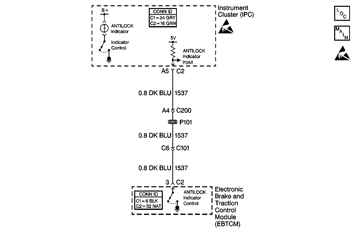
Circuit Description
The instrument cluster controls the operation of the ANTILOCK indicator. The EBTCM reports the desired status of the ANTILOCK indicator via serial data class 2 messages. The hard wired circuit is a back-up reporting circuit. The EBTCM supplies ground through the circuit when the ABS is operating properly. Using the serial data messages and back-up circuit, the instrument cluster decides whether to turn on the ANTILOCK indicator.
Conditions for Setting the DTC
All of the following conditions occur:
| • | The EBTCM commands the ANTILOCK indicator ON. |
| • | The EBTCM detects one of the following conditions in the ANTILOCK indicator control circuit: |
| - | An open |
| - | A short to ground |
| - | A short to voltage |
Actions Taken When the DTC Sets
| • | A malfunction DTC is stored. |
| • | The ABS remains functional. |
| • | For a short, the ABS indicator remains OFF. |
| • | For an open, the ABS indicator is turned ON. |
Conditions for Clearing the DTC
| • | The condition for DTC is no longer present and you used scan tool Clear DTCs function. |
| • | The condition for DTC is no longer present and you used the On-Board Clear DTCs function. |
| • | The EBTCM does not detect the DTC in 50 drive cycles. |
Diagnostic Aids
| • | It is very important that a thorough inspection of the wiring and connectors be performed. Failure to carefully and fully inspect wiring and connectors may result in misdiagnosis, causing part replacement with reappearance of the malfunction. |
| • | An intermittent malfunction can be caused by poor connections, broken insulation, or a wire that is broken inside the insulation. |
| • | If an intermittent malfunction exists, refer to Intermittents and Poor Connections Diagnosis in Wiring Systems. |
Test Description
The numbers below refer to step numbers on the diagnostic table.
-
Checks if the IPC has the ability to operate the ABS indicator lamp.
-
Checks for a short to ground in CKT 1537.
-
Checks for a short to voltage in CKT 1537.
-
Checks for an open in CKT 1537.
Step | Action | Value(s) | Yes | No |
|---|---|---|---|---|
1 | Did you perform the Diagnostic System Check? | -- | Go to Step 2 | Go to Diagnostic System Check |
Did the ABS indicator lamp turn ON then OFF? | -- | Go to Step 3 | Go to Step 9 | |
Is the resistance within the specified range? | OL (infinite) | Go to Step 5 | Go to Step 4 | |
4 | Repair the short to ground in CKT 1537. Refer to Wiring Repairs in Wiring Systems. Did you complete the repair? | -- | Go to Diagnostic System Check | -- |
Is the voltage greater than the specified value? | 1 V | Go to Step 7 | Go to Step 6 | |
Is the resistance less than the specified value? | 5 ohms | |||
7 | Repair the short to voltage in CKT 1537. Refer to Wiring Repairs in Wiring Systems. Did you complete the repair? | -- | Go to Diagnostic System Check | -- |
8 | Repair the open in CKT 1537. Refer to Wiring Repairs in Wiring Systems. Did you complete the repair? | -- | Go to Diagnostic System Check | -- |
9 | Replace the instrument cluster (IPC). Refer to Instrument Cluster Replacement in Instrument, Panel, Gauges and Console. Did you complete the repair? | -- | Go to Diagnostic System Check | -- |
10 | Replace the EBTCM. Refer to Electronic Brake Control Module Replacement . Did you complete the repair? | -- | Go to Diagnostic System Check | -- |
