Rear Disc Brake Pads Replacement Without J55
Removal Procedure
- Remove two-thirds of the brake fluid from the master cylinder.
- Raise the vehicle and suitably support. Refer to Lifting and Jacking the Vehicle in General Information.
- Mark the relationship of the wheel to the hub flange.
- Remove the Wheel. Refer to Tire and Wheel Removal and Installation in Tires and Wheels.
- Using a large C clamp compress the piston into the caliper until resistance is felt, but no more than 1 mm of piston travel in order to gain enough clearance to allow the caliper to pivot off the caliper bracket.
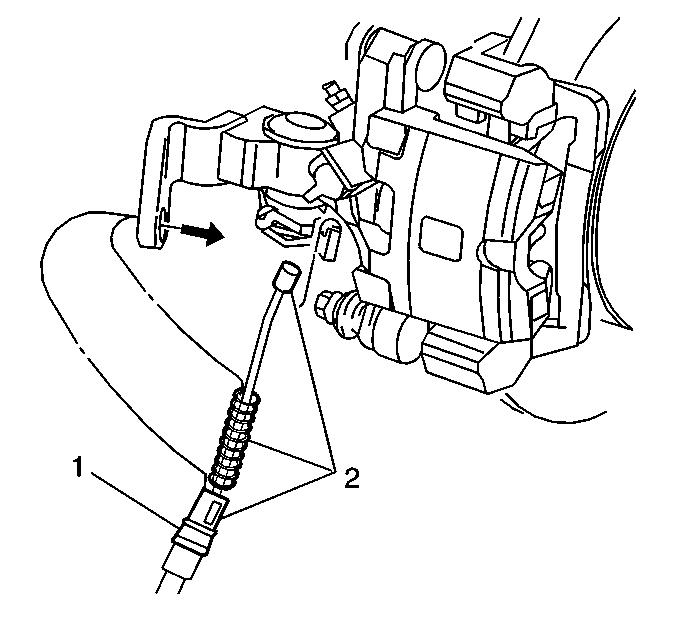
- Disconnect the park brake cable (1) from the brake caliper.
- Remove the bottom caliper pin bolt.
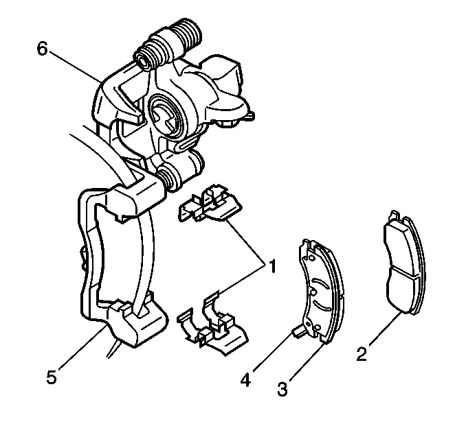
- Pivot the caliper body (6) upward.
- Remove the inboard (2) and outboard (3) pads from the anchor bracket (5).
- Remove and inspect the pad retainers (1).
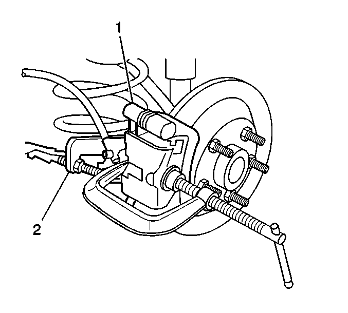
Important: Do not use a screwdriver or pry bar to compress the caliper piston into the caliper. Any damage to the piston boot could cause corrosive elements to enter the piston sealing area and lead to the piston seizing in the caliper bore.
Important: Do not exceed more than 1 mm of piston travel. Damage to the internal adjusting mechanism may result.
Installation Procedure
Important: Inspect the caliper bolt suspension boots for cuts, tears, or deterioration. If damaged, replace the pin boots. Refer to Caliper Bracket Overhaul. Inspect the piston boot for deterioration. If damaged, Refer to Caliper overhaul. Caliper pin bolt for damage or corrosion. Replace if damaged or corroded. Do not attempt to clean away corrosion. Corrosion is typically caused by damaged pin boots.
Important: The electronic brake pad wear sensors must be replaced every time the brake pads are replaced. New brake pad wear sensors are included with GM replacement brake pad kits.
- Retract the caliper piston (2) into the caliper bore. Use a spanner type wrench and turn the piston clockwise until it bottoms out fully in the caliper and align the piston.
- Install the brake pad retainers (1) into the caliper anchor bracket (5).
- Snap the brake pad wear sensor into the inboard brake pad.
- Install the inboard (2) and outboard (3) brake pads into the caliper anchor bracket. Route the wear sensor wire through the caliper and support properly to be sure the wire will lay in its proper location when the caliper is installed.
- Use a small plastic or wooden tool (1) to lift the inner edge of the boot next to the piston, and press out any trapped air.
- Pivot the caliper (6) down over the brake pads (3,2) and into the anchor bracket (5). Be sure that the wear sensor (4) wiring is properly routed and clipped in its original location.
- Insert the lower caliper pin bolt.
- Connect the park brake cable (1) to the brake caliper (2).
- Install the tire and wheel assembly. Refer to Tire and Wheel Removal and Installation
- Lower the vehicle. Refer to Lifting and Jacking the Vehicle in General Information.
- Adjust the brake fluid level.
- Start the vehicle and apply approximately 778 N (175 lb) of force three times to the brake pedal to seat the brake caliper piston and brake pads. This helps to seat the brake caliper and pads.
- Recheck the brake fluid level.
- Burnish the pads and rotors. Refer to Brake Pad and Rotor Burnishing .
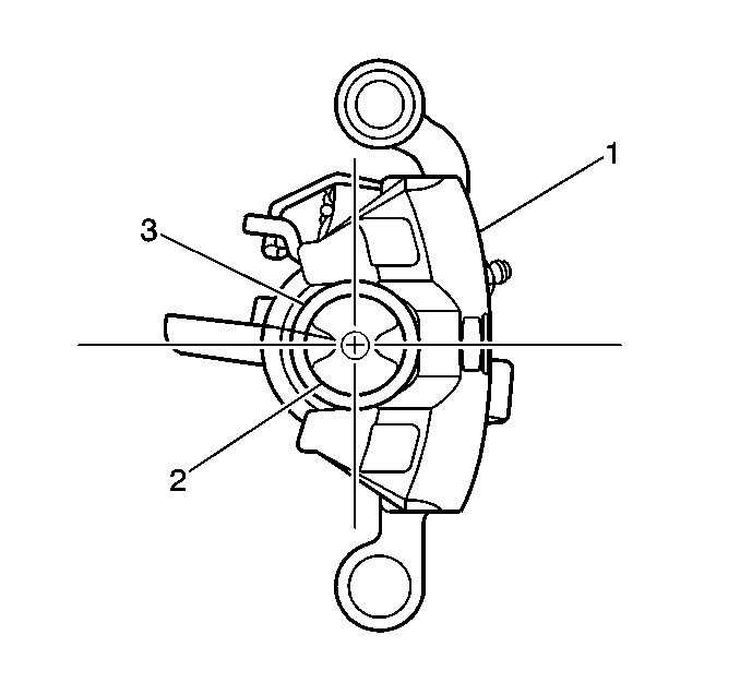


Important: The caliper piston boot must lay flat. Make sure convolutions are tucked into place.

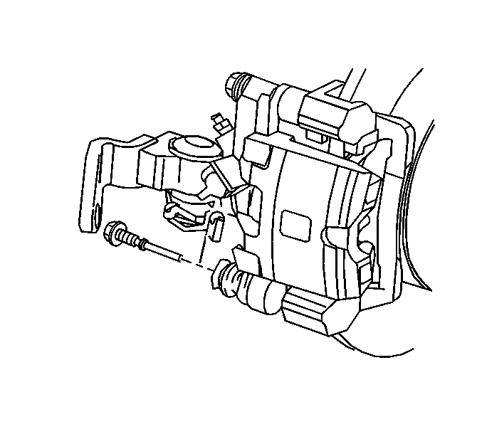
Tighten
Tighten the caliper pin bolt to 26 N·m (20 lb ft).

