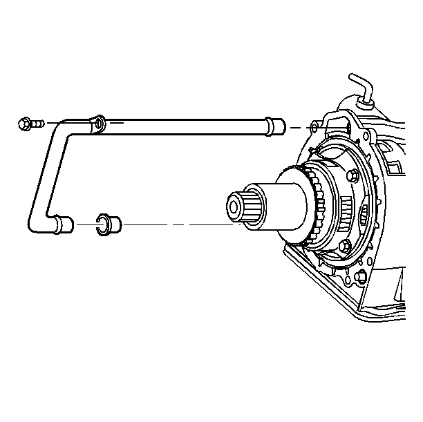
Removal Procedure
Tools Required
J 28467-B Universal
Engine Support Fixture
Caution: Unless directed otherwise, the ignition and start switch must be in the OFF or LOCK position, and all electrical loads must be OFF before servicing
any electrical component. Disconnect the negative battery cable to prevent an electrical spark should a tool or equipment come in contact with an exposed electrical terminal. Failure to follow these precautions may result in personal injury and/or damage to
the vehicle or its components.
- Disconnect the battery negative
cable assembly from the battery negative terminal.
- Raise the vehicle. Refer to
Lifting and Jacking the Vehicle
- Support the vehicle with safety stands.
- Remove the right front wheel and tire. Refer to
Tire and Wheel Removal and Installation
- Remove the right front wheel splash shield. Refer to
Front Bumper Fascia Extension Replacement
- Remove the right stabilizer link at the steering knuckle. Refer
to
Stabilizer Shaft Insulator Replacement
- Remove the right tie rod from the steering knuckle. Refer to
Rack and Pinion Outer Tie Rod End Replacement
- Remove the right ball joint from the steering knuckle. Refer to
with V4U/B9Q or
Lower Control Arm Ball Joint Replacement
- Remove the right drive axle. Refer to
Wheel Drive Shaft Replacement
- Remove the safety stands.
- Lower the vehicle.
Important : Load the support fixture by tightening the wing nuts several turns in
order to take the weight of the powertrain off of the mounts and the frame.

- Install the J 28467-B
.
- Raise the left side of the powertrain (the transmission side)
25.4 mm (1.0 in) above the powertrain resting position with
the adjusting screws.
- Raise the vehicle. Refer to
Lifting and Jacking the Vehicle
.
- Support the vehicle with safety stands.
- Remove the following parts:
| 16.1. | The power steering pressure switch electrical connector |
- Remove the following parts:
| 17.1. | The right transmission mount |
| 17.2. | The bracket connector |
- Remove the following parts:
| 18.1. | The right transmission to engine bracket |
- Remove the following parts:
| 19.1. | The vehicle speed sensor (VSS) electrical connector |
| 19.2. | The ground wire from the case |

- Remove the five case extension
bolts and the stud using a torque wrench.
- Remove the case extension and the seal. The seal may remain in
the extension.
- Remove the roller thrust bearing and the selective washer.

- Remove the scavenger tube
attaching bolt.
- Remove the scavenger tube by prying on the differential.
- Remove the scavenger tube seal.
- Inspect the scavenger tube for damage and clogging.
- Inspect the case extension and the case mating surfaces for scoring
and damage.
- Remove the case extension.

- Remove the following parts:
Installation Procedure

- Install the parking gear
with the thrust bearing.
- Install the snap ring.
- Install the final drive internal gear.
- Install the snap ring.
- Install the sun gear with the bushing and the seal side facing
differential.
- Install the final drive carrier. Turn the unit until it meshes
with the sun gear and the internal gear teeth.
- Install the left thrush washer.
- Install the left deferential side gear.
- Install the snap ring.
- Use the manual shaft to place the transaxle in park.
This will lock up the final drive unit. The actuator rod will move up.
Notice: Use the correct fastener in the correct location. Replacement fasteners
must be the correct part number for that application. Fasteners requiring
replacement or fasteners requiring the use of thread locking compound or sealant
are identified in the service procedure. Do not use paints, lubricants, or
corrosion inhibitors on fasteners or fastener joint surfaces unless specified.
These coatings affect fastener torque and joint clamping force and may damage
the fastener. Use the correct tightening sequence and specifications when
installing fasteners in order to avoid damage to parts and systems.
- Install the differential
housing and the four bolts. Hand tighten, using a star pattern.
Tighten
Tighten the bolts to 76 N·m (56 lb ft).

- Install the scavenger
tube seal into the case.
- Install the scavenger tube into the case. Tap the scavenger tube
in lightly using a plastic hammer. The rib on the pipe will remain exposed.
This is a normal condition.
- Install the scavenger tube bolt.
Tighten
Tighten the bolt to 13 N·m (116 Ib in).

- Install the selective
washer and the thrust roller bearing onto the differential output shaft.
- Insert the case extension seal into the case extension.
- Install the case extension onto the case.
- Install the bolts and the stud. Install the stud in the 11 o'clock
position using the star pattern.
Tighten
Tighten the bolts and the stud to 54 N·m (40 Ib ft).
- Install the vehicle speed sensor (VSS) electrical connector and
the ground wire to the case.
- Install the right transmission to engine bracket and the heat
shield.
- Install the right transmission mount and the bolts.
- Install the power steering pressure switch connector and the wiring
harness.
- Install both drive axles into the transmission. Refer to
Wheel Drive Shaft Replacement
in Wheel Drive Shafts.
- Install the RTD sensor to the lower control arm.
- Install the right front wheel splash shield. Refer to
Front Bumper Fascia Extension Replacement
.
- Install the right front wheel and tire. Refer to
Tire and Wheel Removal and Installation
.
- Remove the safety stands.
- Lower the vehicle.
- Connect the battery negative cable assembly to the battery negative
terminal.
Tighten
Tighten the terminal bolt to 15 N·m (11 lb ft).
- Install the case extension and the scavenger pipe.
- Check the fluid level.
- Reset the Transmission fluid life indicator.


