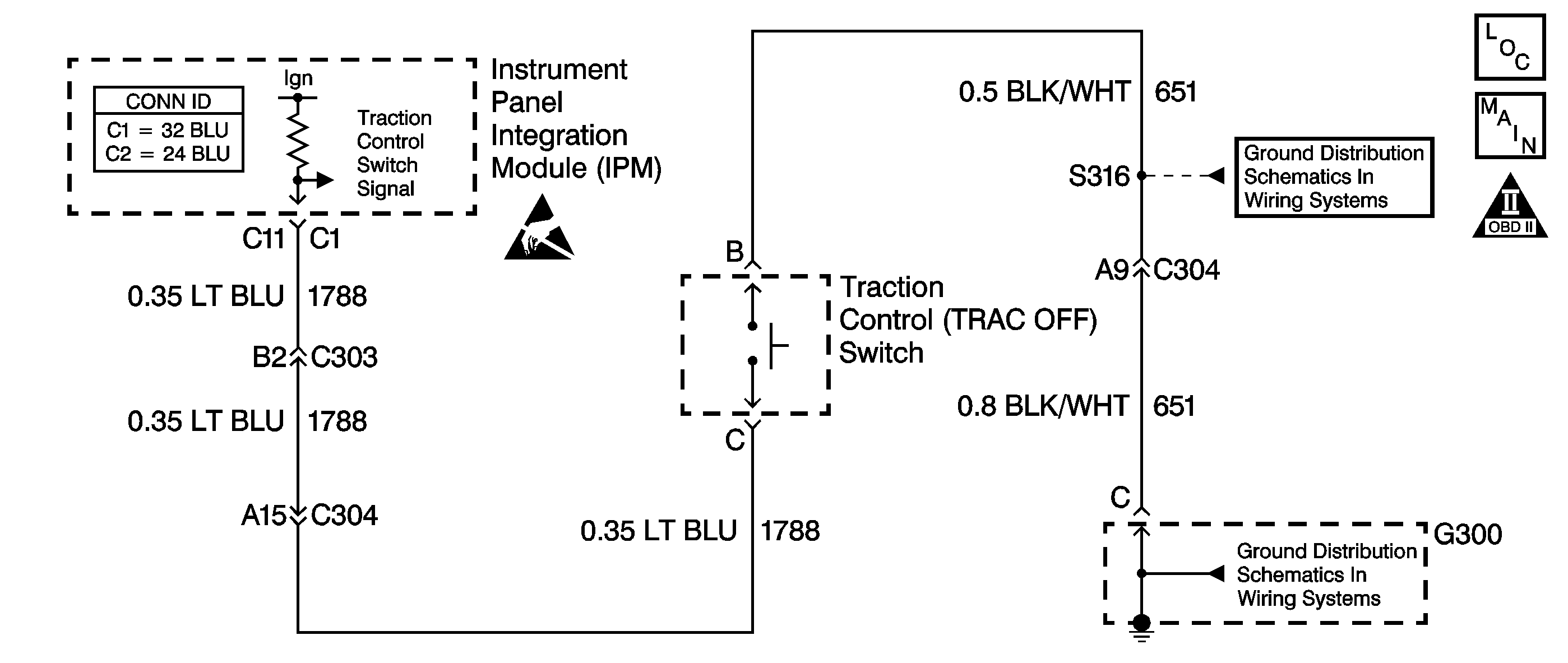
Circuit Description
The traction control (TRAC OFF) switch allows the driver to select a second gear start.
The TRAC OFF switch is a momentary contact switch. Depressing the switch creates a ground path for the instrument panel integration module (IPM) ignition voltage input. When the IPM senses this voltage drop, the module turns OFF the traction control. The IPM sends a serial data message to the electronic brake control module (EBCM). The EBCM sends a serial data message to the PCM. Upon receiving this signal the PCM will command a second gear start for the remainder of the ignition cycle or until the TRAC OFF switch is depressed a second time.
The following ignition cycle, traction control will return to an active state. The transmission will again achieve a first gear start.
The driver information center (DIC) displays the traction control state. When the DIC displays TRACTION READY, the vehicle achieves a first gear start. When the DIC displays TRACTION OFF, the vehicle achieves a second gear start. The DIC will not update the traction status display when the TRAC OFF switch is pushed and a scan tool is installed. After removing the scan tool the ignition must be cycled in order to update the DIC.
Diagnostic Aids
| • | If, in TRACTION OFF mode, the vehicle does not achieve a second gear start, perform the following procedure: |
| - | Select Current Gear on the scan tool. |
| - | Press the TRAC OFF switch once. Observe the display. The scan tool should indicate 1 or 2, depending on the last switch input. |
| • | Inspect the connections at the IPM, the TRAC OFF switch and all other circuit connecting points for an intermittent condition. Refer to Testing for Intermittent Conditions and Poor Connections in Wiring Systems. |
| • | Inspect the circuit wiring for an intermittent condition. Refer to Testing for Electrical Intermittents in Wiring Systems. |
Test Description
-
This step tests for brake system and traction control system DTCs. If an ABS/TCS DTC is set, repair that condition before proceeding.
-
This step tests the function of the switch. If the scan tool display verifies the switch operation, then the condition may be intermittent.
-
This step isolates the switch from the circuit, in order to verify that the signal and ground circuits are working properly. If the displayed status changes, then the circuitry and the PCM are working properly.
-
This step verifies that the signal circuit from the IPM to the switch is working properly.
-
This step replaces the TRAC OFF switch. Previous steps found no fault in the signal or ground circuits.
-
This step road tests the vehicle in both TRACTION OFF and TRACTION READY modes. Monitor the Current Gear display. A difference in acceleration verifies the repair.
Step | Action | Value(s) | Yes | No |
|---|---|---|---|---|
Are any ABS or TCS DTCs displayed? | -- | Go to ABS/TCS Section | ||
Does the Current Gear display change when the switch is pressed? | -- | Go to Diagnostic Aids | ||
Refer to Automatic Transmission Related Connector End Views . Did the Current Gear display change? | -- | |||
Using the J 35616 , connect a fused jumper wire from terminal C of the TRAC OFF switch connector to ground. Refer to Automatic Transmission Related Connector End Views . Did the Current Gear display change? | -- | |||
5 | Test the signal circuit (CKT 1788) of the TRAC OFF switch for an open or short to ground. Refer to Circuit Testing and Wiring Repairs in Wiring Systems. Did you find and correct a condition? | -- | ||
6 | Test the ground circuit (CKT 651) of the TRAC OFF switch for an open. Refer to Circuit Testing and Wiring Repairs in Wiring Systems. Did you find and correct the condition? | -- | ||
Replace the TRAC OFF switch. Refer to Traction Off Switch Replacement. Did you complete the replacement? | -- | -- | ||
8 | Refer to Diagnostic System Check - Body Control System in Body Control System. Did you complete the procedure? | -- | -- | |
Perform the following procedure in order to verify the repair:
Is there a difference in acceleration and performance between the two modes? | -- | System OK |
