For 1990-2009 cars only
Disassembly Procedure
Tools Required
J 24319-01 Universal Steering Linkage Puller
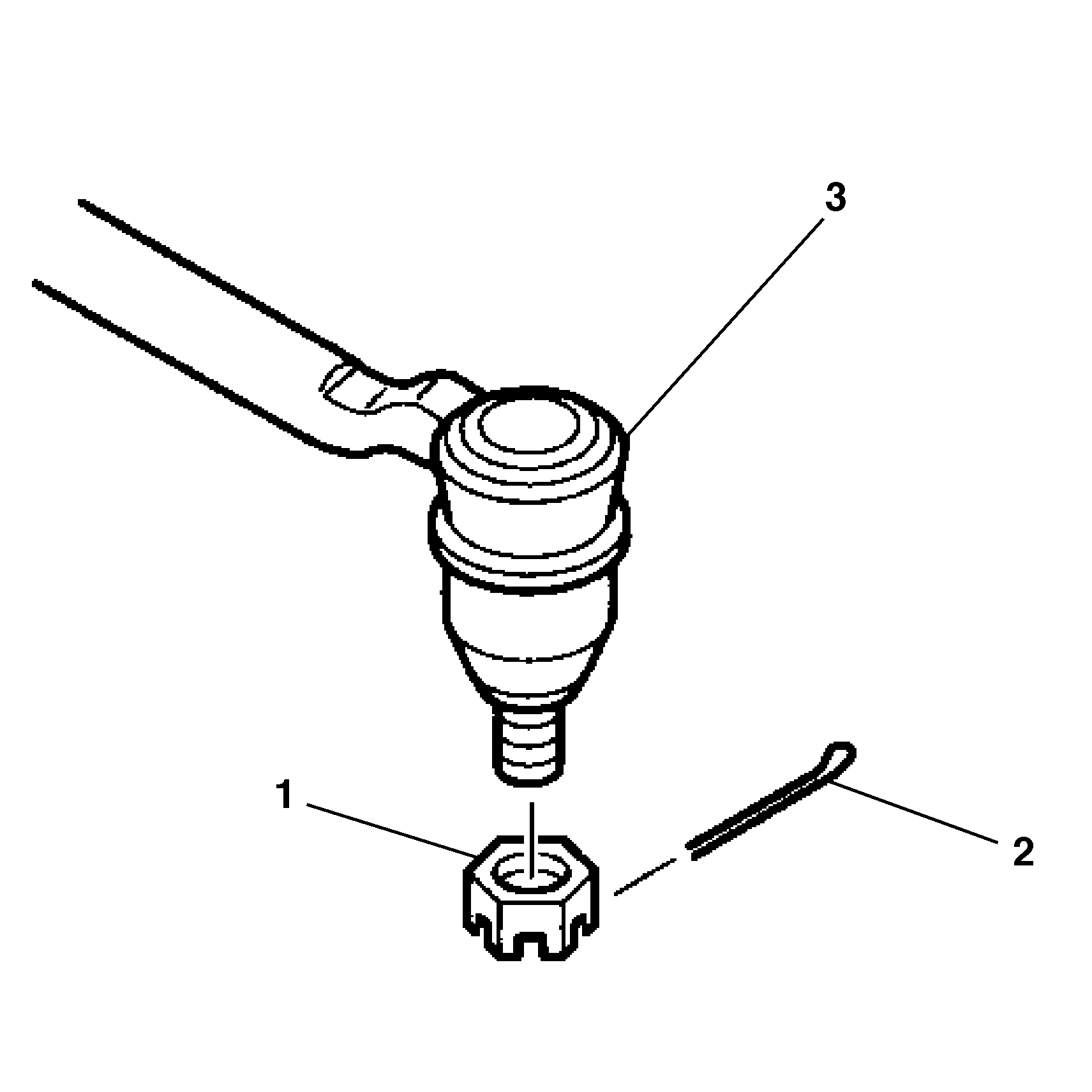
- Pull the cotter pin (2) and the hex slotted nut (1) from outer tie rod assembly (3).
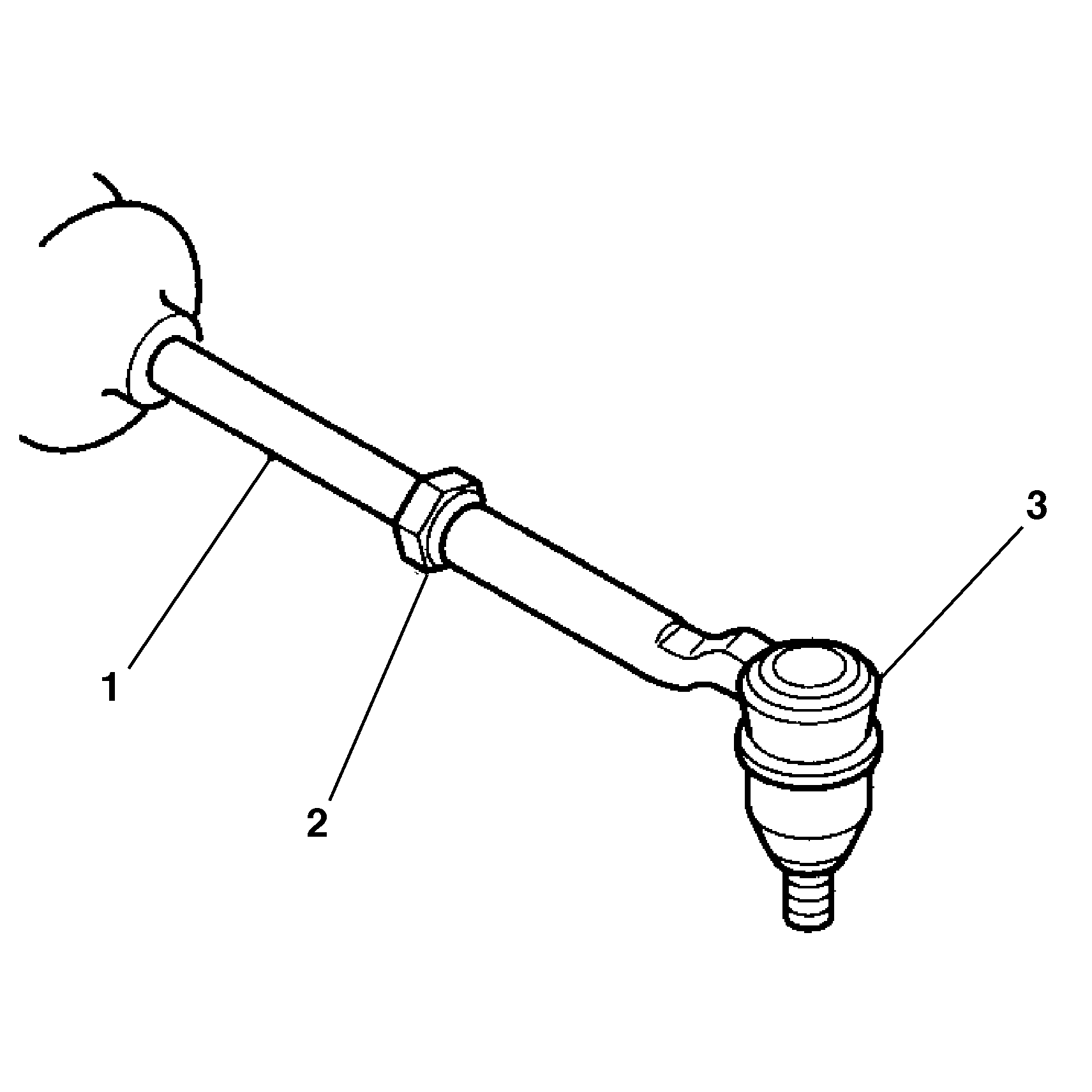
- Loosen the jam nut (2) on the inner tie rod assembly (1).
- Remove the outer tie rod assembly (2) from the steering knuckle (1) using J 24319-01 .
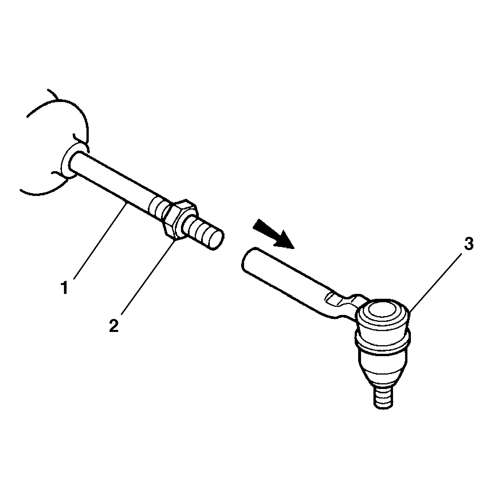
- Remove the outer tie rod assembly (3) from the inner tie rod assembly (1).

Assembly Procedure
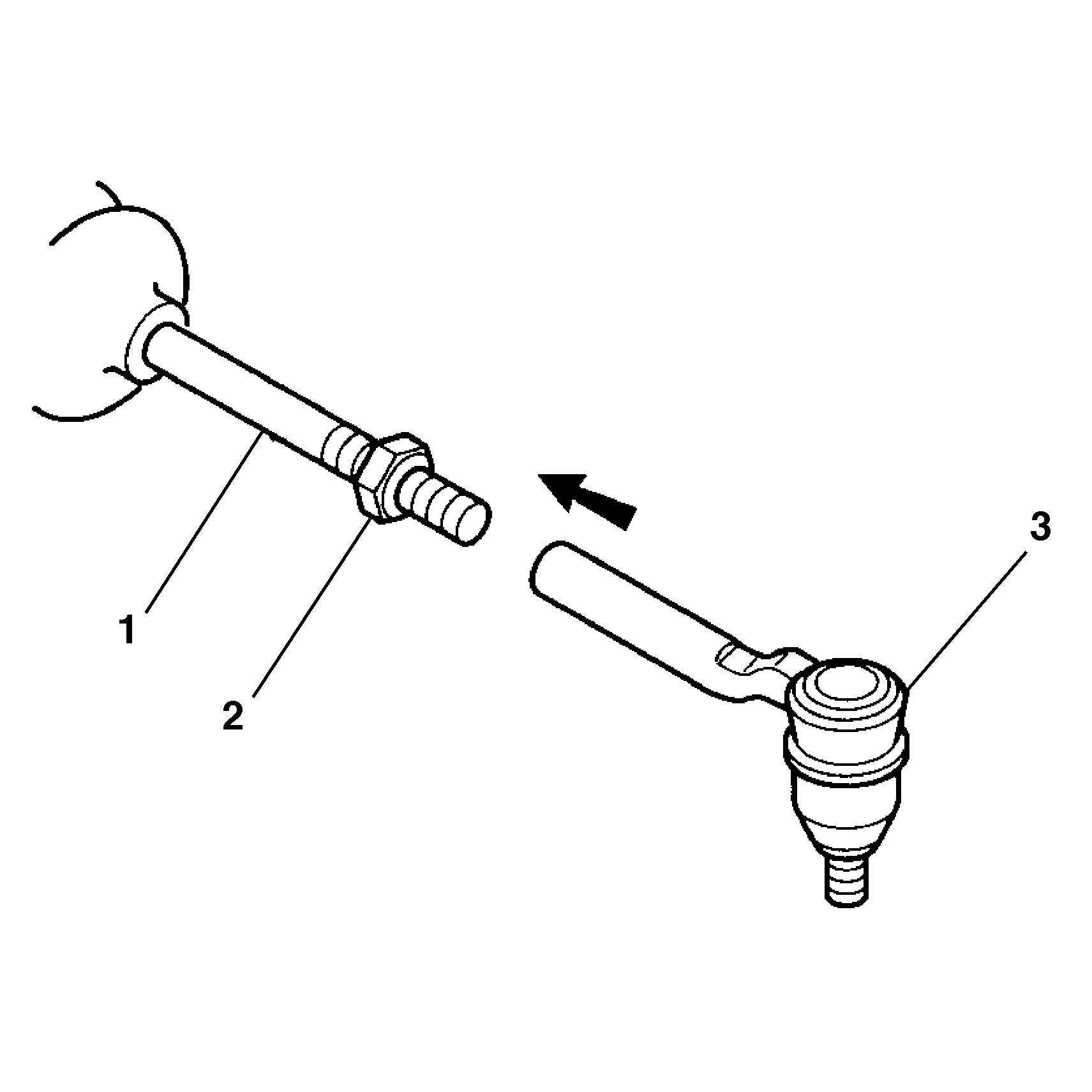
- Connect the outer tie rod assembly (3) to the inner tie rod (1).
- Do not tighten the jam nut (2).
- Connect the outer tie rod assembly (2) to the steering knuckle (1).
- Connect the hex slotted nut (1) to the outer tie rod stud (3).
- .Connect the hex slotted nut (1) to the outer tie rod stud (3).
- Install the cotter pin (2) into the hole in the tie rod stud.
- Adjust toe by turning the inner tie rod. Follow recommended manufacturer specifications.
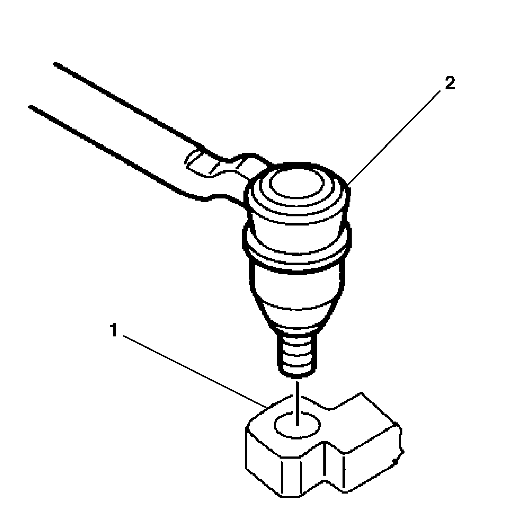
Tighten
Tighten the hex slotted nut (1) to 47 N·m (35 lb ft).
Align the cotter pin slot by tightening the hex slotted nut (1) up
to 1/6 additional turn, or 70 N·m (52 lb ft) maximum.
Do not back off the hex slotted nut (1) for the cotter pin insertion.

Tighten
Tighten the hex slotted nut (1) to 47 N·m (35 lb ft).
Align the cotter pin slot by tightening the hex slotted nut (1) up
to 1/6 additional turn, or 70 N·m (52 lb ft) maximum.
Do not back off the hex slotted nut (1) for the cotter pin insertion.
Important: Be sure the rack and pinion boot is not twisted or puckered during toe adjustment.
Tighten
Tighten the jam nut against the outer tie rod to 68 N·m
(50 lb ft).
