Antenna Assembly Replacement UE1
External Foot with Mast Removal Procedure
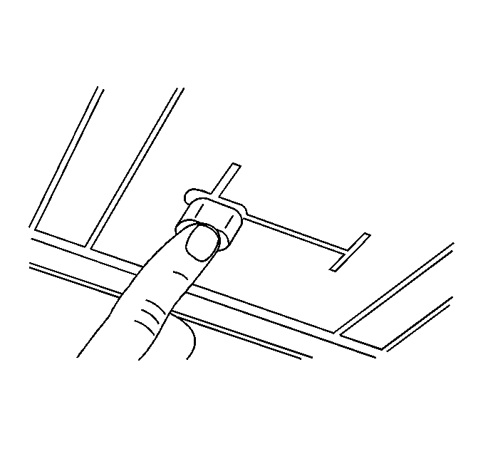
Use a razor blade or a putty knife in order to cut the double back tape material while lifting up on the external foot.
External Foot with Mast Installation Procedure
- Clean the exterior glass and the external foot with alcohol.
- Dry the components thoroughly using a lint-free cloth.
- Apply new double back tape.
- Mount the foot 152 mm (6 in) from the right window edge midway between the antenna gridline and the defogger gridline.
- Press firmly on all 4 corners in order to ensure proper bonding between the adhesive and the glass.

Interior Coupling Box Removal Procedure
Disconnect coaxial cable from the internal coupling box.
Use a razor blade or a putty knife in order to cut the double back tape material while lifting up on the internal coupling box.
Interior Coupling Box Installation Procedure
- Clean the interior glass and the coupling box with alcohol.
- Dry the components thoroughly using a lint-free cloth.
- Apply new double-back tape.
- Align the interior coupling box with the exterior mount.
- Press the interior coupling box onto the back window using even firm pressure at all 4 corners.

Important: The RF connections for the interior coupling box should run parallel to the defogger gridline.
Coaxial Cable Removal Procedure
- Remove the coaxial cable from the cell phone antenna.
- Remove the rear seat back. Refer to Rear Seat Back Replacement in Seats.
- Remove right rear sail panel. Refer to Sail Panel Replacement in Interior Trim.
- Remove the rear shelf panel. Refer to Rear Window Shelf Trim Panel Replacement in Interior Trim.
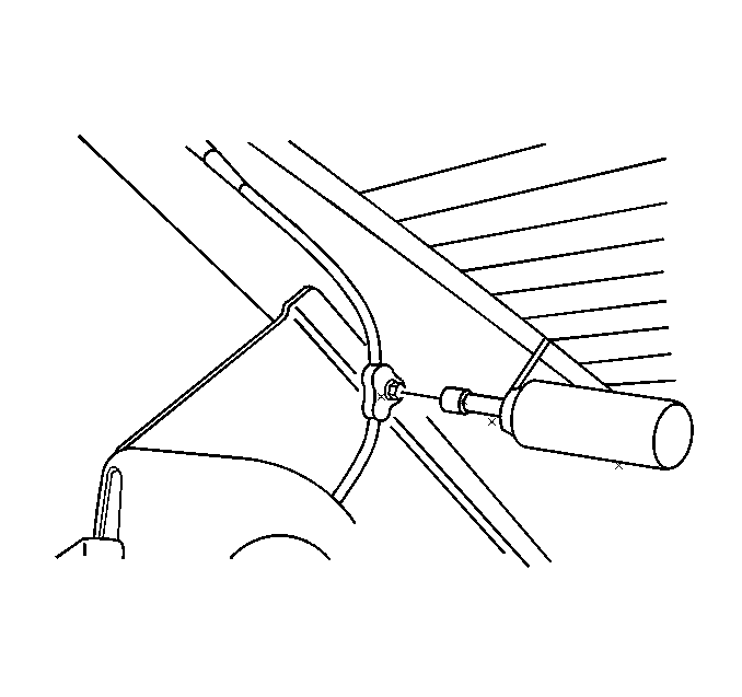
- Remove the defogger module ground bolt retaining the coaxial cable to the body.
- Remove the rear compartment trim. Refer to Rear Compartment Trim Panel Replacement in Body Rear End.
- Remove the coaxial cable from the cellular telephone module and the RF booster, if equipped.
- Remove the coaxial cable from the vehicle.

Coaxial Cable Installation Procedure
- Install the coaxial cable to the cellular telephone module and the RF booster, if equipped.
- Route the coaxial cable to the interior coupling box.
- Install the defogger module ground bolt through the coaxial cable hold down.
- Install the defogger ground bolt.
- Install the rear compartment trim. Refer to Rear Compartment Trim Panel Replacement in Body Rear End.
- Install the rear shelf panel. Refer to Rear Window Shelf Trim Panel Replacement in Interior Trim.
- Install the rear seat back. Refer to Rear Seat Back Replacement in Seats.
- Install the sail panel. Refer to Sail Panel Replacement in Interior Trim.

Notice: Use the correct fastener in the correct location. Replacement fasteners must be the correct part number for that application. Fasteners requiring replacement or fasteners requiring the use of thread locking compound or sealant are identified in the service procedure. Do not use paints, lubricants, or corrosion inhibitors on fasteners or fastener joint surfaces unless specified. These coatings affect fastener torque and joint clamping force and may damage the fastener. Use the correct tightening sequence and specifications when installing fasteners in order to avoid damage to parts and systems.
Tighten
Tighten the bolts to 1.6 N·m (14 lb in)
Antenna Assembly Replacement UV8
Removal Procedure
- Remove the rear seat back. Refer to Rear Seat Back Replacement in Seats.
- Remove the right side sail panel. Refer to Sail Panel Replacement in Interior Trim.
- Disconnect the cellular phone antenna cable connection (1), located behind the rear seat back.
- Remove the rear window defroster/cellular phone antenna ground fastener (2) which grounds the cellular phone antenna and the rear window defroster.
- Peel the cellular phone antenna (1) from the inside surface of the backglass.
- Remove the cellular phone antenna (1) from the vehicle.


The rear window defroster/cellular phone antenna ground fastener (2) is located behind the right side sail panel.

Notice: If you use a razor blade or other sharp tool in order to remove the adhesives or foreign objects from the inside of the rear window, use the blade carefully. Damage to the grid lines may result.
A razor blade or a putty knife may be necessary in order to remove the antenna from the backglass.
Installation Procedure
- Connect the cellular phone antenna cable connection (1).
- Install the cellular phone antenna cable/rear window defroster ground fastener (2) through the rear window defroster and the cellular phone ground eyelet (1).
- Install the cellular phone antenna cable ground/rear window defroster fastener (2) to the body.
- Clean the inside surface of the backglass, where the cellular phone antenna is to be mounted, below the defroster grid on the right side of the vehicle.
- Assemble the new antenna cable to the new antenna loop.
- Use soapy water when installing the cellular phone antenna to the backglass in order to ease installation and allow for positioning of the antenna during installation.
- Install the cellular phone antenna to the inside of the backglass, 102 mm (4 in) (a) from the blackout line on the right side and approximately 9.5 mm (3/8 in) (b) below the defroster grid.
- Clean excess soapy water from the backglass.
- Install the right side sail panel. Refer to Sail Panel Replacement in Interior Trim.
- Install the rear seat back. Refer to Rear Seat Back Replacement in Seats.


Notice: Refer to Fastener Notice in the Preface section.
Tighten
Tighten the fastener to 9 N·m (80 lb in).

Important: The new cellular phone coaxial antenna cable and the cellular phone antenna loop will need to be assembled.
Ensure the new antenna cable is attached to the antenna loop on the printed side, the side of the loop opposite the paper film that is peeled to adhere the antenna to the backglass, in order to ensure the electrical connection to the cellular phone antenna. Ensure the contacts touch the metal strips on the antenna loop. If the electrical connection to the antenna loop is not properly attached the cellular phone will have poor or no reception when the phone is docked and plugged into the vehicle system.A small amount of dish soap works well for this application.
