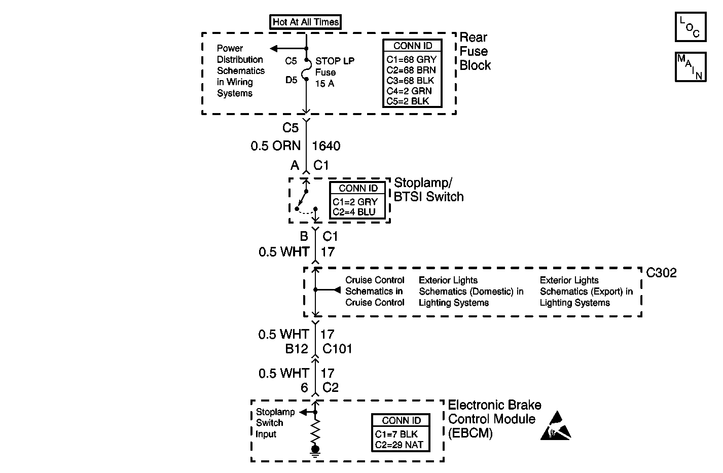
Circuit Description
The EBCM uses this stoplamp switch circuit for various performance measures within DRP/ABS/TCS/VSES. This DTC is set if the EBCM has determined that the stoplamp switch is continously ON. TCS cannot be activated when the stoplamp switch is ON
Conditions for Running the DTC
The vehicle speed is greater than 40 km/h (25 mph).
Conditions for Setting the DTC
The stop lamp switch input was active for 2 consecutive ignition cycles.
Action Taken When the DTC Sets
| • | The EBCM disables the TCS for the duration of the ignition cycle. |
| • | The TRACTION CONTROL indicator turns ON. |
| • | The ABS remains functional. |
Conditions for Clearing the DTC
| • | The condition for the DTC is no longer present and the DTC is cleared with a scan tool. |
| • | The EBCM automatically clears the history DTC when a current DTC is not detected in 100 consecutive drive cycles. |
Diagnostic Aids
Possible causes of this DTC are the following conditions:
| • | The stop lamp switch circuit is shorted to voltage. |
| • | The stop lamp switch is misadjusted. |
| • | The stop lamp switch is stuck closed. |
| • | A brake pedal that is binding. |
| • | Both brake light bulbs are burned out. |
Test Description
The numbers below refer to the step numbers on the diagnostic table.
-
Tests the circuit for a change in states.
-
Tests for proper operation of the circuit by bypassing the stoplamp switch. If the fuse in the jumper opens when you perform this test, the signal circuit of the stoplamp switch is shorted to ground.
Step | Action | Yes | No | ||||
|---|---|---|---|---|---|---|---|
Schematic Reference: Antilock Brake System Schematics | |||||||
1 | Did you perform the ABS Diagnostic System Check? | Go to Step 2 | |||||
2 | Press the brake pedal. Do the brake lamps turn ON? | Go to Step 3 | Go to Step 7 | ||||
Does the Stop Lamp Switch parameter change state? | Go to Diagnostic Aids | Go to Step 4 | |||||
4 |
Did you find and correct the condition? | Go to Step 13 | Go to Step 5 | ||||
Does the scan tool display Applied? | Go to Step 10 | Go to Step 6 | |||||
6 | Test the signal circuit of the stop lamp switch for an open between the splice pack of the stop lamp signal circuit and the EBCM. Refer to Circuit Testing and Wiring Repairs in Wiring Systems. Did you find and correct the condition? | Go to Step 13 | Go to Step 9 | ||||
7 | Test the signal circuit of the stop lamp switch for an open between the stop lamp switch and the splice of the stop lamp signal circuit. Refer to Circuit Testing and Wiring Repairs in Wiring Systems. Did you find and correct the condition? | Go to Step 13 | Go to Step 8 | ||||
8 | Test the signal circuit of the stop lamp switch for a short to ground. Refer to Circuit Testing and Wiring Repairs in Wiring Systems. Did you find and correct the condition? | Go to Step 13 | Go to Step 9 | ||||
9 | Inspect for poor connections at the harness connector of the EBCM. Refer to Testing for Intermittent Conditions and Poor Connections and Connector Repairs in Wiring Systems. Did you find and correct the condition? | Go to Step 13 | Go to Step 11 | ||||
10 | Inspect for poor connections at the harness connector of the stoplamp switch. Refer to Testing for Intermittent Conditions and Poor Connections and Connector Repairs in Wiring Systems. Did you find and correct the condition? | Go to Step 13 | Go to Step 12 | ||||
11 |
Important: Perform the setup procedure for the EBCM. An unprogrammed EBCM will result
in the following conditions:
Replace the EBCM. Refer to Electronic Brake Control Module Replacement . Did you complete the repair? | Go to Step 13 | -- | ||||
12 | Replace the stop lamp switch. Refer to Stop Lamp Switch Replacement in Hydraulic Brakes. Did you complete the repair? | Go to Step 13 | -- | ||||
13 |
Does the DTC reset? | Go to Step 2 | System OK | ||||
