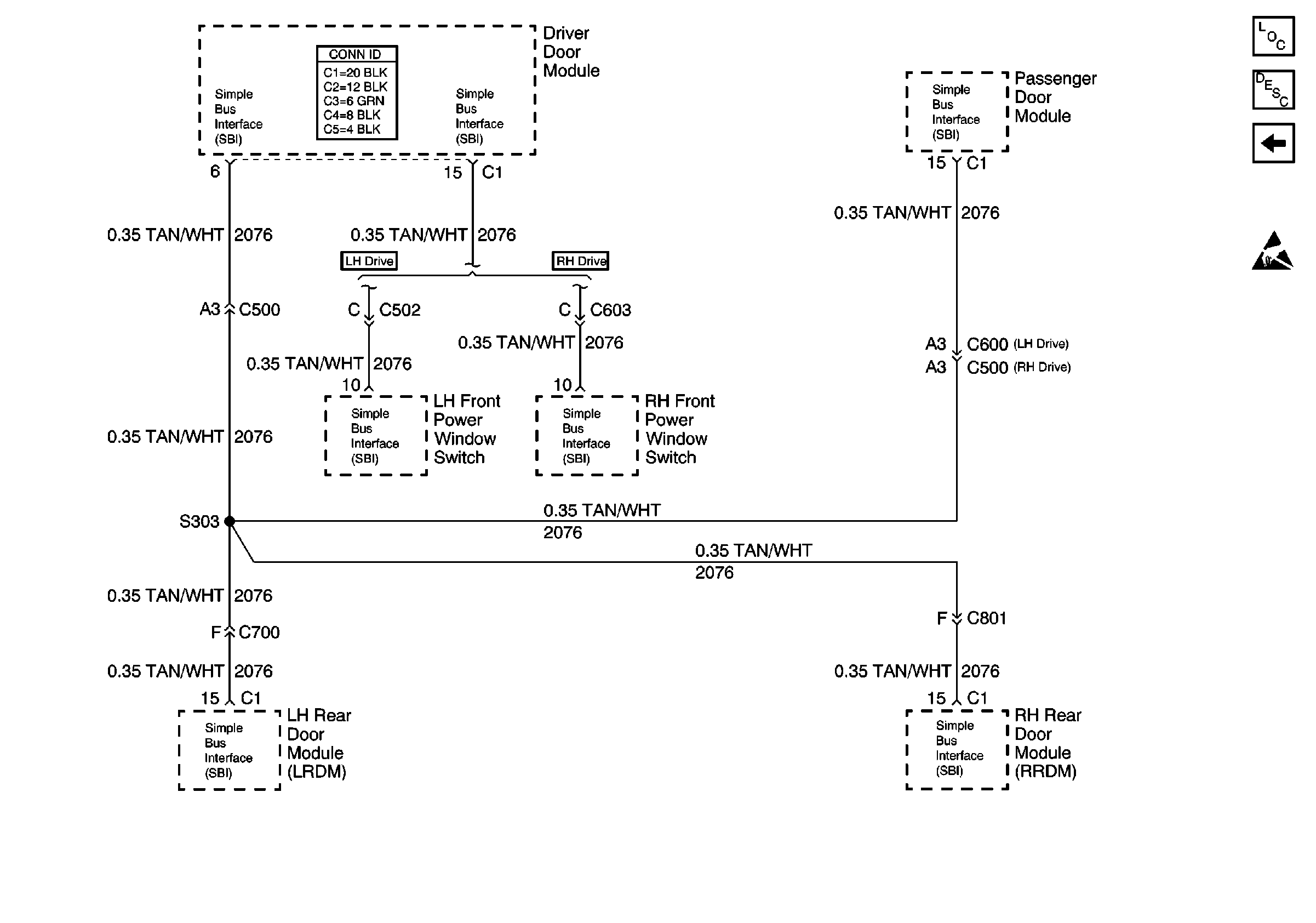
Refer to
Simple Bus Interface (SBI)

.
Circuit Description
The simple bus interface (SBI) data line communicates information between the door modules. Each module connected to the SBI is assigned a recognition code, or address. This code is used in order to identify which modules are communicating. Modules communicate with each other by periodically sending state of health (SOH) messages. When the ignition switch is in RUN, each module communicating on the SBI sends a SOH message every 2 seconds. This ensures that the system is operating properly. When the front LH power window switch stops communicating the SOH messages that is normally sent disappears. The driver door module (DDM) which expects to receive that message detects the absence of the message and sets DTC U1170.
Conditions for Running the DTC
| • | The DDM does not receive an SOH message back from the LH front power window switch. |
| • | The DTC only sets if U1300 or U1301 are not current. |
Action Taken When the DTC Sets
| • | DTC U1170 is stored in the DDM. |
| • | The DDM uses the default values for the initialization data. |
| • | This DTC does not cause a driver warning message to appear. |
Conditions for Clearing the DTC
This DTC clears (status changes from current to history) under any of the following conditions:
| • | The DDM detects an SOH message from the LH front power window switch. |
| • | At each ignition cycle. |
Diagnostic Aids
| • | DTC module U1170 does not normally represent a failure within the module. |
| • | If the DTC is a history DTC, the problem may be intermittent. |
Step | Action | Value(s) | Yes | No |
|---|---|---|---|---|
1 | Did you perform Diagnostic System Check - Power Door Systems ? | -- | Go to Step 2 | |
2 | Are DTCs U1161, U1162 and U1163 also current? | -- | Go to Step 6 | Go to Step 3 |
3 | Test for an open in CKT 2076 (TAN/WHT) between connector C1 terminal 15 of the driver door module (DDM) and the LH front power window switch (w/LH drive) or the RH front power window switch (w/RH drive). Refer to Wiring Repairs in Wiring Systems. Did you find and correct the condition? | -- | Go to Step 23 | Go to Step 4 |
4 | Test the voltage and ground circuits to the LH front power window switch (w/LH drive) or the RH front power window switch (w/RH drive). Refer to Wiring Repairs in Wiring Systems. Did you find and correct the condition? | -- | Go to Step 23 | Go to Step 5 |
5 | Replace theLH front power window switch. Refer to Front Door Switch Replacement . Is the repair complete? | -- | Go to Step 23 | -- |
6 |
Is the voltage within the specified range? | 10-15 V | Go to Step 8 | Go to Step 7 |
7 |
Is the resistance within the specified range? | 0-2ohms | Go to Step 9 | Go to Step 10 |
8 |
Is the voltage within the specified range? | 10-15 V | Go to Step 18 | Go to Step 5 |
9 |
Is the resistance within the specified range? | 0-2ohms | Go to Step 18 | Go to Step 5 |
10 |
Is the voltage within the specified range? | 10-15 V | Go to Step 11 | Go to Step 12 |
11 |
Is the resistance within the specified range? | 0-2ohms | Go to Step 15 | Go to Step 19 |
12 |
Is the voltage within the specified range? | 10-15 V | Go to Step 13 | Go to Step 20 |
13 |
Is the voltage within the specified range? | 10-15 V | Go to Step 14 | Go to Step 21 |
14 |
Is the voltage within the specified range? | 10-15 V | Go to Step 18 | Go to Step 22 |
15 |
Is the resistance within the specified range? | 0-2ohms | Go to Step 16 | Go to Step 20 |
16 |
Is the resistance within the specified range? | 0-2ohms | Go to Step 17 | Go to Step 21 |
17 |
Is the resistance within the specified range? | 0-2ohms | Go to Step 18 | Go to Step 22 |
18 | Repair the short in CKT 2076 (TAN/WHT). Refer to Wiring Repairs . Is the repair complete? | -- | Go to Step 23 | -- |
19 | Replace the DDM. Refer to Door Control Module Replacement in Doors. Is the repair complete? | -- | Go to Step 23 | -- |
20 | Replace the PDM. Refer to Door Control Module Replacement in Doors. Is the repair complete? | -- | Go to Step 23 | -- |
21 | Replace the LRDM. Refer to Door Control Module Replacement in Doors. Is the repair complete? | -- | Go to Step 23 | -- |
22 | Replace the RRDM. Refer to Door Control Module Replacement in Doors. Is the repair complete? | -- | Go to Step 23 | -- |
23 |
Are all of the DTCs cleared? | -- | -- |
