For 1990-2009 cars only
Removal Procedure
Caution: When you are performing service on or near the SIR components or the SIR wiring, you must disable the SIR system. Refer to Disabling the SIR System. Failure to follow the correct procedure could cause air bag deployment, personal injury, or unnecessary SIR system repairs.
- Disable the SIR. Refer to Disabling the SIR System .
- Remove the center console. Refer to Console Replacement .
- Remove the right and the left insulator panels. Refer to Instrument Panel Insulator Panel Replacement - Left Side or Instrument Panel Insulator Panel Replacement - Right Side .
- Remove the left and the right instrument panel (IP) endcaps. Refer to Instrument Panel Outer Trim Cover Replacement .
- Remove the passenger side inflator module. Refer to Inflatable Restraint Instrument Panel Module Replacement in SIR.
- Remove the right IP accessory trim plate. Refer to Instrument Panel Accessory Trim Plate Replacement - Right Side .
- Remove the IP cluster. Refer to Instrument Cluster Replacement .
- Remove the radio or the navigation display module. Refer to Radio Replacement or Navigation Display Module Replacement in Entertainment.
- Remove the A/C heater control head. Refer to Control Assembly Replacement in Heating, Ventilation, and Air Conditioning.
- Remove the steering column. Refer to Steering Column Replacement in Steering Wheel and Column.
- Remove the headlamp switch. Refer to Headlamp Switch Replacement in Lighting Systems.
- Remove the fuel/rear compartment release switch. Refer to Fuel/Rear Compartment Release Switch Replacement .
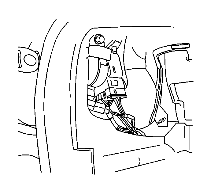
- Disconnect the ignition switch electrical connector.
- Disconnect the park lock cable from the ignition switch. Refer to Park Lock Cable Replacement in Automatic Transmission.
- Remove the IP storage compartment. Refer to Instrument Panel Compartment Replacement .
- Remove the IP retaining screws from the ends of the retainer.
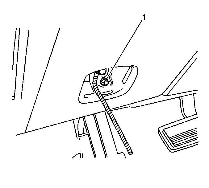
- Remove the fasteners from the IP retainer. One fastener (1) is located in the opening for the fuel/rear compartment release switch.
- Remove the retaining bolts from the IP retainer to the lower support bracket.
- Remove the IP retainer from the carrier. Feed the wiring through the openings as necessary.


Disconnect the inside air temperature sensor electrical connector.
Remove the IP assembly.
Installation Procedure
- Partially install the IP retainer to the carrier.
- Guide the wiring through the IP retainer openings.
- Install the retaining bolts from the IP retainer to the lower support bracket.
- Install the fasteners to the IP retainer. One fastener (1) is located in the opening for the fuel/rear compartment release switch.
- Install the IP retaining screws into the ends of the retainer.
- Install the IP storage compartment. Refer to Instrument Panel Compartment Replacement .
- Connect the park lock cable to the ignition switch. Refer to Park Lock Cable Replacement .
- Connect the ignition switch electrical connector.
- Install the fuel/rear compartment release switch. Refer to Fuel/Rear Compartment Release Switch Replacement .
- Install the headlamp switch. Refer to Headlamp Switch Replacement in Lighting Systems.
- Install the steering column. Refer to Steering Column Replacement in Steering Wheel and Column.
- Install the AC/heater control head. Refer to Control Assembly Replacement in Heating, Ventilation, and Air Conditioning.
- Install the radio or the navigation display module. Refer to Radio Replacement or Navigation Display Module Replacement in Entertainment.
- Install the IP cluster. Refer to Instrument Cluster Replacement .
- Install the right IP accessory trim plate. Refer to Instrument Panel Accessory Trim Plate Replacement - Right Side .
- Install the passenger side inflator module. Refer to Inflatable Restraint Instrument Panel Module Replacement in SIR.
- Install the left and the right closeout/insulator panel. Refer to Instrument Panel Insulator Panel Replacement - Left Side or Instrument Panel Insulator Panel Replacement - Right Side .
- Install the center console. Refer to Console Replacement .
- Enable the SIR. Refer to Enabling the SIR System in SIR.
Connect the inside air temperature sensor electrical connector.
Align the IP retainer with the carrier. Complete the installation.


