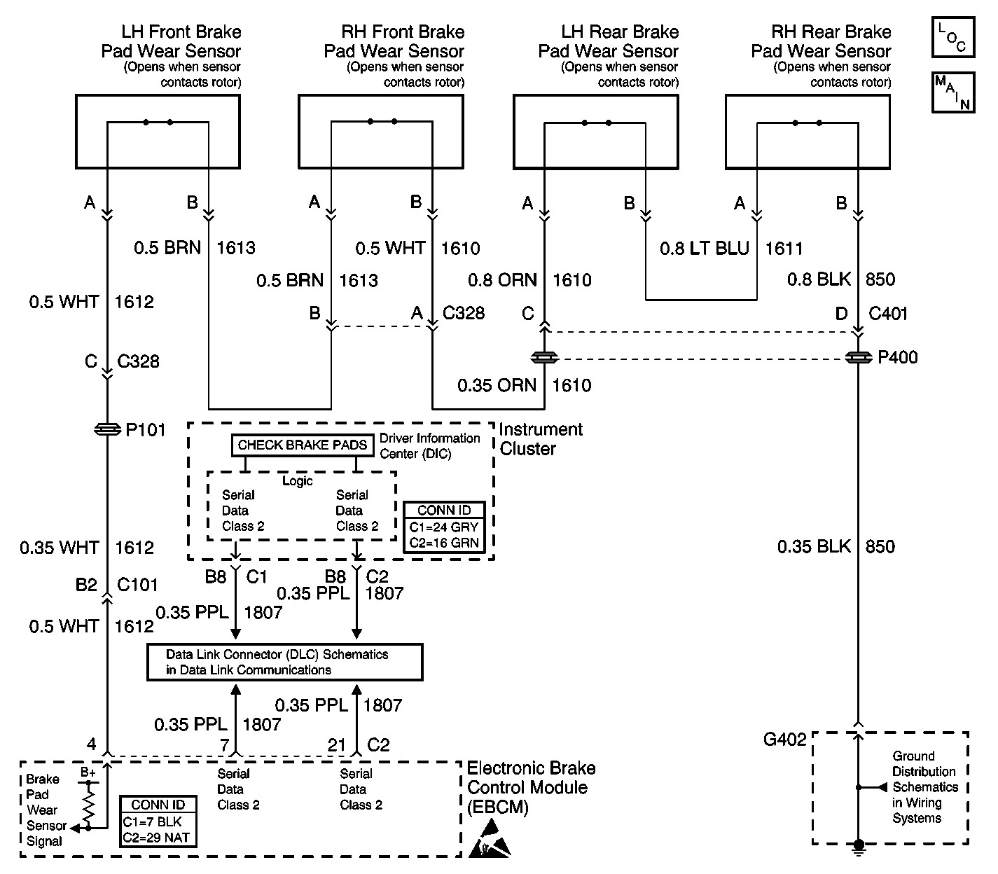
Circuit Description
The brake pad wear senor signal is normally grounded at the EBCM through the brake pad wear sensors in a series circuit.
Conditions for Running the DTC
The stoplamp switch is open.
Conditions for Setting the DTC
The brake pad wear sensor signal voltage is greater than 2.93 volts for 1 second.
Actions Taken When the DTC Sets
The DIC displays the Check Brake Pads message.
Conditions for Clearing the DTC
| • | The condition for the DTC is no longer present and the DTC is cleared with a scan tool. |
| • | The EBCM automatically clears the history DTC when a current DTC is not detected in 100 consecutive drive cycles. |
Step | Action | Value(s) | Yes | No | ||||||
|---|---|---|---|---|---|---|---|---|---|---|
1 | Did you perform the ABS Diagnostic System Check? | -- | Go to Step 2 | |||||||
2 | Since most occurrences of this DTC are caused by worn brake pads, inspect all brake pads and replace if needed. Refer to Brake Pad Inspection and Brake Pads Replacement in Disc Brakes. Did you find and correct the condition? | -- | Go to Step 9 | Go to Step 3 | ||||||
3 |
Does the scan tool display indicate that the Electronic Brake Lining Wear parameter is OK? | -- | Go to Step 7 | Go to Step 4 | ||||||
4 |
Does the scan tool display indicate that the Electronic Brake Lining Wear parameter is OK? | -- | Go to Step 8 | Go to Step 5 | ||||||
5 |
Does the scan tool display indicate that the Electronic Brake Lining Wear parameter is OK? | -- | Go to Step 8 | Go to Step 6 | ||||||
6 |
Does the scan tool display indicate that the Electronic Brake Lining Wear parameter is OK? | -- | Go to Step 8 | Go to Step 9 | ||||||
7 | Test the ground circuit of the RH rear brake pad wear signal circuit for an open. Refer to Circuit Testing and Wiring Repairs in Wiring Systems. Did you find and correct the condition? | -- | Go to Step 14 | Go to Step 10 | ||||||
8 | Test the brake pad wear signal circuit for an open between the currently disconnected brake pad wear sensor and the previously disconnected sensor. Refer to Circuit Testing and Wiring Repairs in Wiring Systems. Did you find and correct the condition? | -- | Go to Step 14 | Go to Step 10 | ||||||
9 | Test the brake pad wear signal circuit for an open between the LH front brake pad wear sensor and the EBCM. Refer to Circuit Testing and Wiring Repairs in Wiring Systems. Did you find and correct the condition? | -- | Go to Step 9 | Go to Step 11 | ||||||
10 | Inspect for poor connections at the harness connector of the brake pad wear sensor that was last disconnected. Refer to Testing for Intermittent Conditions and Poor Connections and Connector Repairs in Wiring Systems. Did you find and correct the condition? | -- | Go to Step 14 | Go to Step 12 | ||||||
11 | Inspect for poor connections at the harness connector of the EBCM. Refer to Testing for Intermittent Conditions and Poor Connections and Connector Repairs in Wiring Systems. Did you find and correct the condition? | -- | Go to Step 14 | Go to Step 13 | ||||||
12 | Replace the brake pad wear sensor that was last disconnected. Refer to Brake Pads Replacement in Disc Brakes. Did you complete the repair? | -- | Go to Step 14 | -- | ||||||
13 |
Important: Perform the setup procedure for the EBCM. An unprogrammed EBCM will
result in the following conditions:
Replace the EBCM. Refer to Electronic Brake Control Module Replacement . Did you complete the repair? | -- | Go to Step 14 | -- | ||||||
14 |
Does the DTC reset? | -- | Go to Step 2 | System OK |
