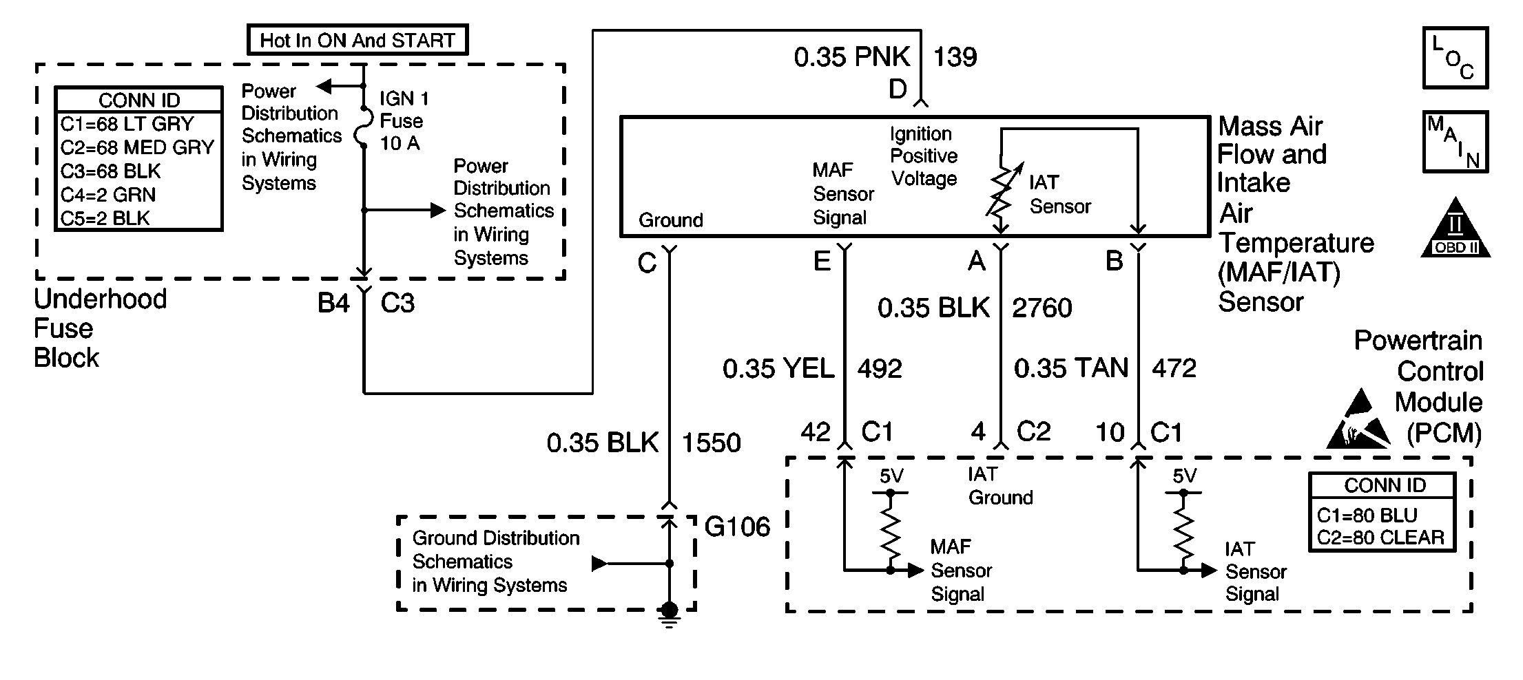
Circuit Description
The mass air flow (MAF) sensor is an air flow meter that measures the flow rate and density of the air entering the engine. The MAF sensor receives power and ground from circuits not supplied by the control module. The control module does apply a voltage to the sensor on the signal circuit. The sensor uses the voltage to produce a frequency based on inlet air flow through the sensor. A low air flow rate (such as engine idle) causes the MAF sensor to produce a low frequency signal. A high air flow rate (such as wide open throttle, or high load) causes the MAF sensor to produce a high frequency signal.
The PCM uses the MAF sensor signal to provide the correct fuel delivery for a wide range of engine speeds and loads. If the PCM detects a signal frequency lower than the possible range of a normally operating MAF sensor, DTC P0102 will set.
Conditions for Running the DTC
| • | TP sensor, MAP sensor, or System Voltage DTCs are not set. |
| • | Engine speed is more than 400 RPM. |
| • | System voltage is more than 10.5 volts. |
Conditions for Setting the DTC
| • | MAF sensor signal is less than 1135 Hz. |
| • | The condition exists for at least 3 seconds. |
Action Taken When the DTC Sets
| • | The PCM illuminates the malfunction indicator lamp (MIL) during the second consecutive trip in which the diagnostic test runs and fails. |
| • | The PCM stores the conditions present when the DTC set as Freeze Frame/Failure Records data. |
Conditions for Clearing the MIL/DTC
| • | The PCM will turn the MIL OFF after the third consecutive trip in which the diagnostic runs and passes. |
| • | The history DTC will clear after 40 consecutive warm-up cycles have occurred without a malfunction. |
| • | The DTC can be cleared by using the scan tool Clear DTC Information function. |
Diagnostic Aids
For intermittent conditions, refer to Symptoms .
Step | Action | Values | Yes | No | ||||||
|---|---|---|---|---|---|---|---|---|---|---|
1 | Did you perform the Powertrain On-Board Diagnostic (OBD) System Check? | -- | ||||||||
2 |
Is the MAF frequency less than the specified value? | 1135 Hz (1.1 kHz) | ||||||||
3 |
Does the scan tool indicate that DTC P0102 failed this ignition? | -- |
Go to Diagnostic Aids | |||||||
4 |
Is the voltage between the specified values? | 4-6 volts | ||||||||
5 |
Is the voltage more than the specified value? | 10 volts | ||||||||
6 |
Is the voltage more than the specified value? | 10 volts | ||||||||
7 |
Did you find and correct the condition? | -- | ||||||||
8 | Locate and repair the open MAF sensor ignition feed circuit. Refer to Wiring Repairs in Wiring Systems. Is the action complete? | -- | -- | |||||||
9 | Locate and repair the open or high resistance condition in the MAF sensor ground circuit. Refer to Wiring Repairs in Wiring Systems. Is the action complete? | -- | -- | |||||||
10 |
Did you find and correct the condition? | -- | ||||||||
11 | Replace the MAF sensor. Refer to Mass Airflow Sensor/Intake Air Temperature Sensor Replacement . Is the action complete? | -- | -- | |||||||
12 |
Did you find and correct the condition? | -- | ||||||||
13 |
Important: The replacement PCM must be programmed. Replace the PCM. Refer to Powertrain Control Module Replacement/Programming . Is the action complete? | -- | -- | |||||||
14 |
Does the scan tool indicate the DTC P0102 passed? | -- | System OK |
