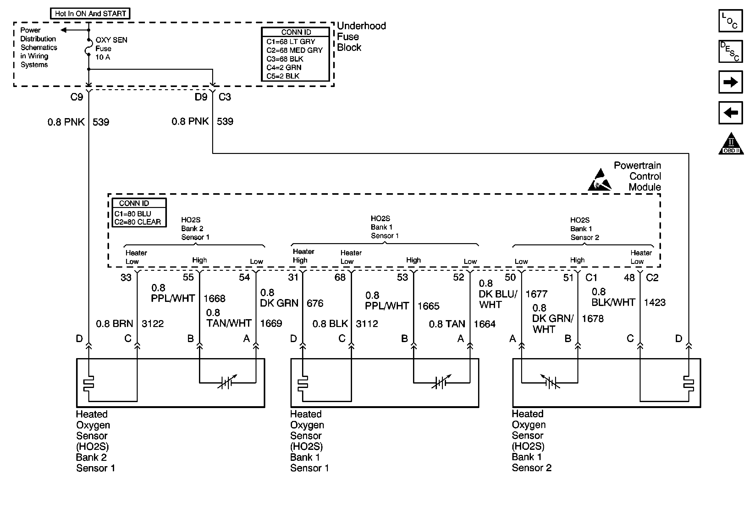
Refer to Engine Controls Schematics
HO2S

.
Circuit Description
The oxygen sensor heater is a device used to reduce the time that the sensor takes to go active. The PCM controls the fuel control oxygen sensor heaters using three separate drivers. The PCM uses a current monitoring driver to test the condition of the heaters. A high side driver provides HO2S bank 1 sensor 1 heater with ignition voltage. A fused ignition feed provides bank 2 sensor 1 with ignition voltage. Both heater receive ground through a low side driver (warm-up driver).
With the engine running, the PCM turns ON the high side, and the low side driver to warm-up the oxygen sensors. When the proper conditions are present, the PCM keeps the high side driver ON, turns ON the current monitor driver, and then turns OFF the warm-up driver. This allows the PCM to record a total current value for both of the fuel control heaters. If the test conditions remain stable, the PCM enters the second stage of the test. During this stage, the PCM keeps the current monitor ON, and turns OFF the high side driver. This allows the PCM to record a current value for the bank 2 sensor 1 heater circuit. The PCM subtracts the bank 2 sensor 1 current value from the total current value to determine the current value for bank 1 sensor 1. If the PCM detects a bank 2 sensor 1 current value outside the calibrated range, DTC P0155 will set.
Conditions for Running the DTC
| • | HO2S heater DTCs are not set. |
| • | The System voltage during the current measurement is steady within 1 volt of actual system voltage. |
| • | Engine speed is between 500 and 3000 RPM. |
| • | MAF is between 4 and 30 g/s. |
| • | HO2S Overtemp control is inactive. |
Conditions for Setting the DTC
The PCM detects a bank 1 sensor 1 current value outside the calibrated range.
Action Taken When the DTC Sets
| • | The PCM illuminates the malfunction indicator lamp (MIL) during the second consecutive trip in which the diagnostic test runs and fails. |
| • | The PCM stores the conditions present when the DTC set as Freeze Frame and Fail Records data. |
Conditions for Clearing the MIL/DTC
| • | The PCM will turn the MIL OFF after the third consecutive trip in which the diagnostic runs and passes. |
| • | The history DTC will clear after 40 consecutive warm-up cycles have occurred without a malfunction. |
| • | The DTC can be cleared by using the scan tool Clear DTC Information function. |
Diagnostic Aids
Notice: Do not solder heated oxygen sensor wires. Soldering the wires will result in the loss of the air reference to the sensor. Refer to Engine Electrical for proper wire and connection repair techniques.
If the condition is intermittent, refer to Intermittent Conditions .
Step | Action | Values | Yes | No |
|---|---|---|---|---|
1 | Did you perform the Powertrain On Board Diagnostic (OBD) System Check? | -- | Go to Step 2 | |
2 |
Are DTCs P0030, P1031, and P1032 set? | -- | Go to Step 3 | |
3 |
Are DTCs P0135 and P0155 set? | -- | Go to Step 4 | |
4 | Is DTC P0155 set? | -- | Go to Step 5 | Go to Intermittent Conditions |
5 | Is OXY SEN 1 fuse open? | -- | Go to Step 6 | Go to Step 7 |
6 |
Did you find and correct the condition? | -- | Go to Step 15 | Go to Step 13 |
7 |
Caution: Avoid contact with moving parts and hot surfaces while working around a running engine in order to prevent physical injury. Is the voltage near the specified value? | 5V | Go to Step 9 | Go to Step 8 |
8 |
Did you find and correct the condition? | -- | Go to Step 15 | Go to Step 11 |
9 | With a test lamp connected to ground, probe the supply voltage circuit at the HO2S bank 2 sensor 1 harness connector, fuse side. Refer to Wiring Repairs in Wiring Systems. Does the test lamp illuminate? | -- | Go to Step 10 | Go to Step 12 |
10 | Inspect for poor connections at the harness connector of the HO2S bank 2 sensor 1. Refer to Testing for Intermittent Conditions and Poor Connections and Connector Repairs in Wiring Systems. Did you find and correct the condition? | -- | Go to Step 15 | Go to Step 13 |
11 | Inspect for poor connections at the harness connector of the PCM . Refer to Testing for Intermittent Conditions and Poor Connections and Connector Repairs in Wiring Systems. Did you find and correct the condition? | -- | Go to Step 15 | Go to Step 14 |
12 | Repair the open HO2S bank 2 sensor 1 heater supply voltage circuit. Did you complete the repair? | -- | Go to Step 15 | -- |
13 | Replace HO2S bank 2 sensor 1. Refer to Heated Oxygen Sensor Replacement - Bank 2 . Did you complete the replacement? | -- | Go to Step 15 | -- |
14 |
Important: The replacement PCM must be programmed. Replace the PCM. Refer Powertrain Control Module Replacement/Programming . Did you complete the replacement? | -- | Go to Step 15 | -- |
15 |
Does the scan tool display the DTC ran and passed? | -- | System OK | Go to Step 2 |
