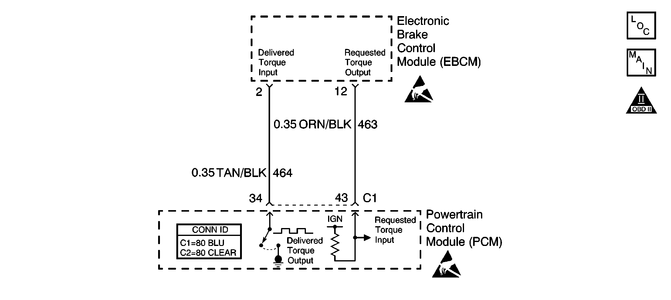
Circuit Description
This diagnostic test checks for a traction control system Desired Torque signal failure to the PCM. The PCM sends 5 volts on the Desired Torque circuit (CKT 463) to the electronic brake and traction control module (EBCM). The EBCM then rapidly switches this CKT to ground creating a PWM frequency signal to request a specific amount of torque reduction during a traction control event. If this PWM signal is not received by the PCM for 3 seconds, DTC P1571 is set.
Conditions for Running the DTC
| • | The traction control not failed. |
| • | The engine speed more than 500 RPM for 20 seconds. |
Conditions for Setting the DTC
PWM, frequency, signal not received on desired torque circuit for 3 seconds.
Action Taken When the DTC Sets
| • | The powertrain control module (PCM) stores the DTC information into memory when the diagnostic runs and fails. |
| • | The malfunction indicator lamp (MIL) will not illuminate. |
| • | The PCM records the operating conditions at the time the diagnostic fails. The PCM stores this information in the Failure Records. |
| • | PCM disables first gear starts. |
| • | Transaxle shift adapts are maintained at current levels. |
Conditions for Clearing the MIL/DTC
| • | A History DTC will clear after forty consecutive warm-up cycles, if no failures are reported by this or any other non-emission related diagnostic. |
| • | A last test failed (Current DTC) will clear when the diagnostic runs and does not fail. |
| • | Use a scan tool in order to clear the MIL/DTC. |
| • | Interrupting the PCM battery voltage may or may not clear DTCs. This practice is not recommended. Refer to Powertrain Control Module (PCM) , Clearing Diagnostic Trouble Codes. |
Diagnostic Aids
This DTC may set along with several others if the key is held in the Crank position while the engine is running. The starter lockout function of the PCM is enabled several seconds after the engine is running and will prevent the starter from engaging while the engine is running. This will cause a partial loss of power to some components and systems.
If no fault is present refer to the Diagnostic System Check - ABS to aid in isolating an intermittent fault.
If the problem is intermittent, refer to Intermittent Conditions .
Test Description
The numbers below refer to the step numbers on the diagnostic table.
Step | Action | Values | Yes | No | ||||||
|---|---|---|---|---|---|---|---|---|---|---|
1 | Did you perform the Powertrain On-Board Diagnostic (OBD) System Check? | -- | ||||||||
2 |
Has this DTC passed? | -- | Go to Diagnostic Aids | |||||||
Is the frequency near the value specified? | 128 Hz | |||||||||
4 | Check for poor connections/terminal tension at the EBTCM. Refer to Testing for Intermittent Conditions and Poor Connections in Wiring Systems. Did you find and correct the condition and corrected? | -- | Go to Diagnostic Starting Point in Antilock Brake System | |||||||
5 |
Did you find and correct the condition and corrected? | -- | ||||||||
6 | Check for poor connections/terminal tension at the PCM. Refer to Testing for Intermittent Conditions and Poor Connections in Wiring Systems. Did you find and correct the condition and corrected? | -- | ||||||||
7 |
Important: The replacement PCM must be programmed. Replace the PCM. Refer to Powertrain Control Module Replacement/Programming . Is the action complete? | -- | -- | |||||||
8 |
Does the scan tool indicate that this test ran and passed? | -- | ||||||||
9 | Review Captured Info using the scan tool. Are there any DTCs that have not been diagnosed? | -- | System OK |
