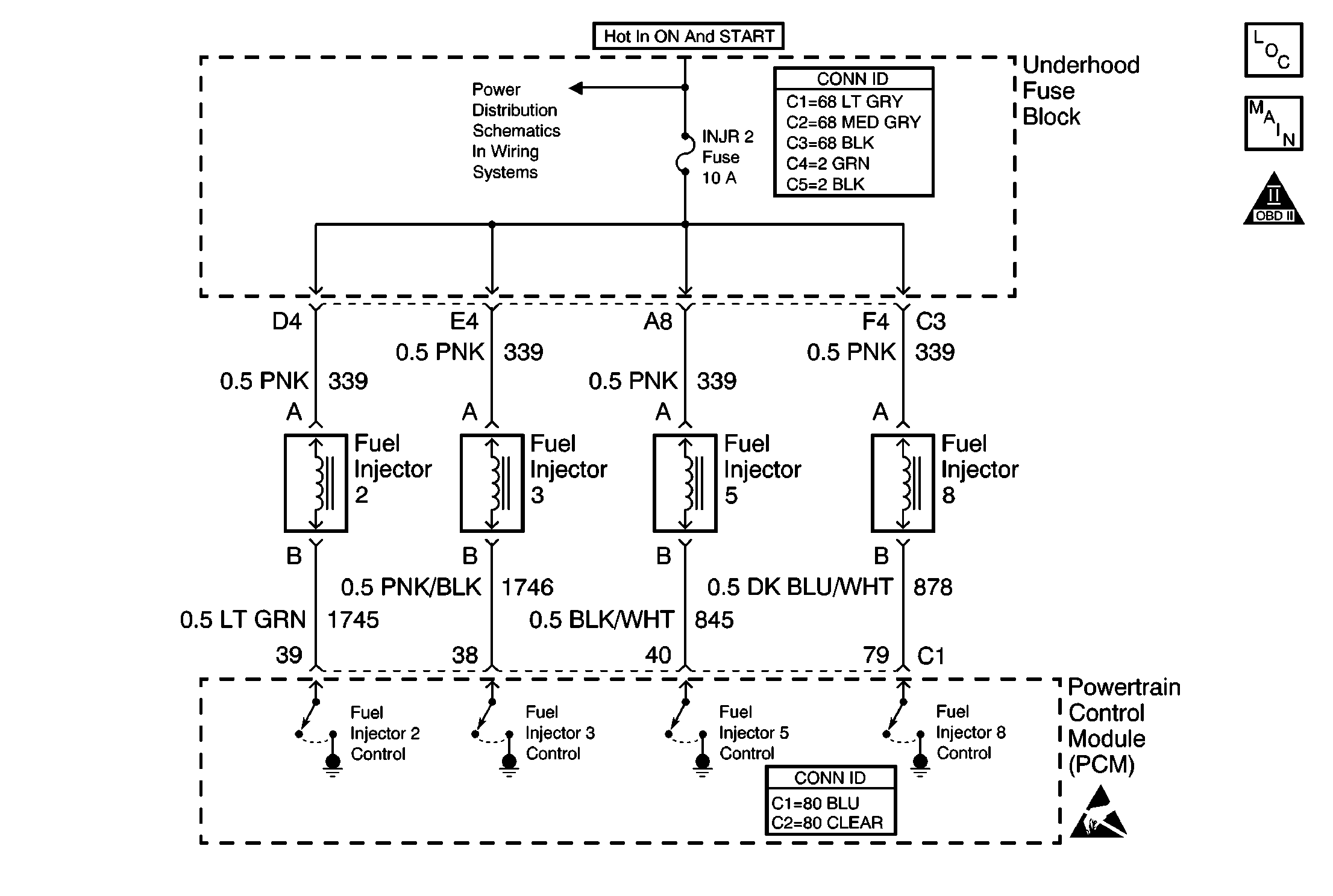
Circuit Description
The fuel injector is a solenoid operated device. The fuel injectors receive 12 volts from the ignition switch through a fuse. The PCM provides the ground path for each injector through individual driver circuits. The PCM monitors the circuits for proper voltage levels. When an improper voltage level occurs, the driver signals the PCM. If the PCM detects an improper voltage level in the fuel injector circuit for cylinder #2, DTC P0202 will set.
Conditions for Running the DTC
| • | System voltage DTCs are not set. |
| • | System voltage between 11-16 volts. |
Conditions for Setting the DTC
The PCM detects an improper voltage level in the fuel injector circuit for cylinder #2.
Action Taken When the DTC Sets
| • | The PCM illuminates the malfunction indicator lamp (MIL) the first time the malfunction is detected. |
| • | The PCM will store the conditions present when the DTC set as Freeze Frame and Fail Records data. |
Conditions for Clearing the MIL/DTC
| • | The PCM will turn the MIL OFF after three consecutive trips during which the diagnostic runs and passes. |
| • | The History DTC clears after 40 consecutive warm-up cycles occur without a malfunction. |
| • | The DTC can be cleared by using the scan tool Clear DTC Information function. |
Diagnostic Aids
If the condition is intermittent, refer to Intermittent Conditions .
Test Description
The numbers below refer to the step numbers in the diagnostic table.
-
If DTCs P0203, P0205, and P0208 are not set, then the malfunction is isolated to fuel injector #1.
-
This determines if the circuit is shorted. An open ignition feed circuit or a faulty splice is indicated if the DTCs are set and the fuse is OK.
-
Checks whether the ignition feed or the fuel injector is shorted.
-
Checks for a short to voltage on the fuel injector control circuit.
-
Checks for an open or short to ground in the fuel injector control circuit.
-
Checks whether the fuel injector is open or if poor terminal contact exists.
-
This vehicle is equipped with a PCM which utilizes an electrically erasable programmable read only memory (EEPROM). When the PCM is replaced, the new PCM must be programmed.
Step | Action | Values | Yes | No | ||||
|---|---|---|---|---|---|---|---|---|
1 | Did you perform the Powertrain On Board Diagnostic (OBD) System Check? | -- | ||||||
2 | With the engine idling, view the DTC Information. Does the scan tool indicate that DTC P0202 failed last test? | -- | ||||||
3 |
Does the scan tool indicate that DTC P0201 failed last test? | -- | Go to Diagnostic Aids | |||||
Are DTCs P0203, P0205, and P0208 also set? | -- | |||||||
Check for an open injector fuse. Is the injector fuse open? | -- | |||||||
Did you find and correct the condition? | -- | Go to Fuel Injector Solenoid Coil Test - Engine Coolant Temperature Between 10-35 Degrees C (50-95 Degrees F) or Fuel Injector Solenoid Coil Test - Engine Coolant Temperature Outside 10-35 Degrees C (50-95 Degrees F) | ||||||
7 |
Does the DMM display a voltage near the specified value? | B+ | ||||||
Does the DMM display a voltage near the specified value? | B+ | |||||||
Did you find and correct the condition? | -- | |||||||
Does the DMM display a voltage near the specified value? | B+ | |||||||
11 |
Did you find and correct the condition? | -- | ||||||
12 |
Did you find and correct the condition? | -- | ||||||
13 | Locate and repair the open circuit or faulty splice connection in the fuel injector #2 feed circuit. Refer to Connector Repairs in Wiring Systems. Is the action complete? | -- | -- | |||||
14 | Locate and repair the short to voltage in the fuel injector #2 control circuit. Refer to Wiring Repairs in Wiring Systems. Is the action complete? | -- | -- | |||||
15 | Locate and repair the open or faulty splice connections in the fuel injector feed circuit. Refer to Wiring Repairs in Wiring Systems. Is the action complete? | -- | -- | |||||
16 | Replace fuel injector #2. Refer to Fuel Injector Replacement . Is the action complete? | -- | -- | |||||
|
Important: The replacement PCM must be programmed. Replace the PCM. Refer to Powertrain Control Module Replacement/Programming . Is the action complete? | -- | -- | ||||||
18 |
Does the scan tool indicate that DTC P0202 passed? | -- | System OK |
