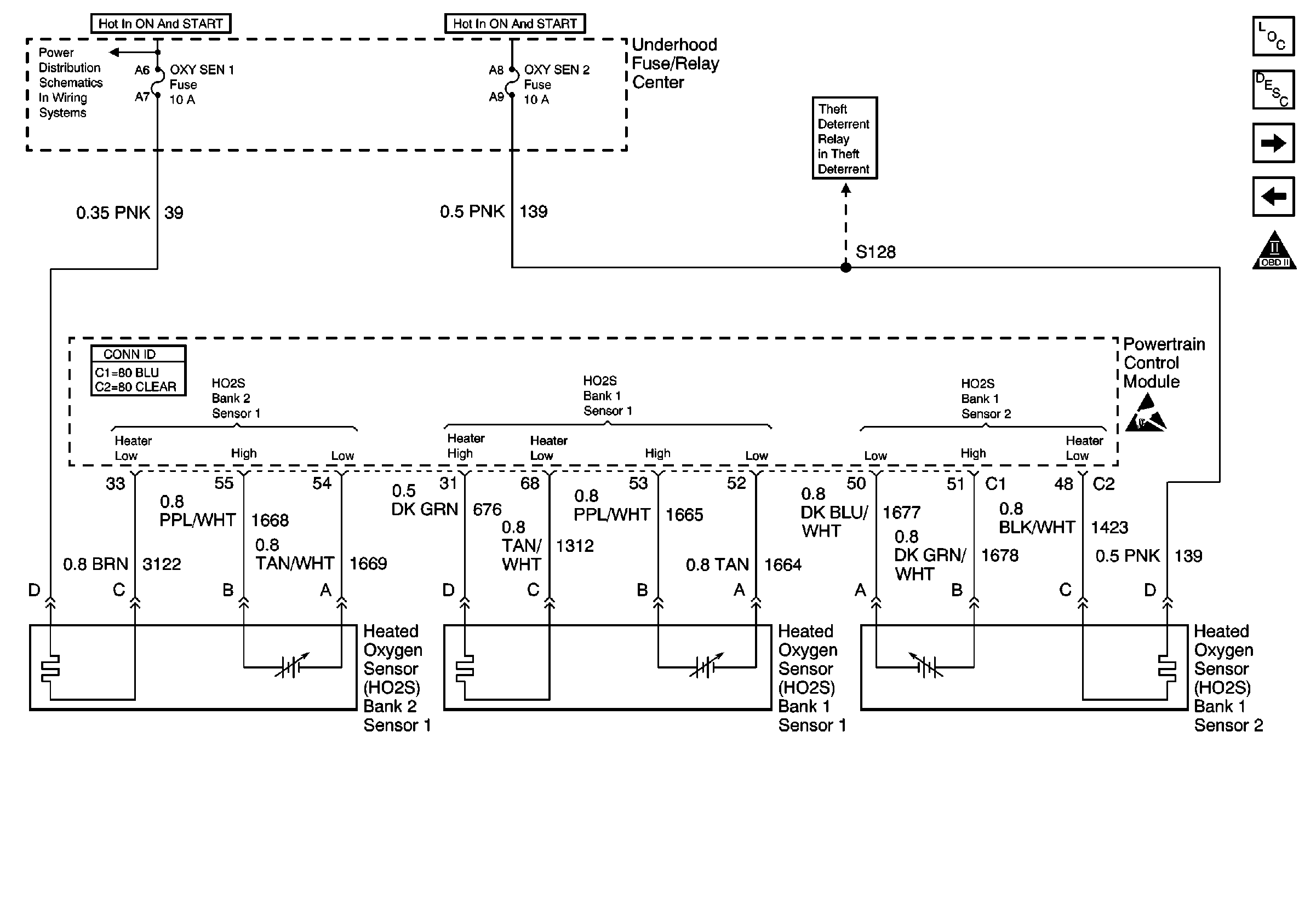
Refer to Engine Controls Schematics
Heated Oxygen Sensors

.
Circuit Description
The oxygen sensor heater is a device used to reduce the time that the sensor takes to go active. The bank 1 sensor 2 heater helps to maintain the sensor at the proper temperature for catalyst testing, and additional adjustments to fuel trim. The bank 1 sensor 2 heater receives power through a fused ignition circuit. The PCM turns the heater ON, and OFF using a low side driver (ODM) located within the PCM.
The PCM will test the heater only after a cold start. The PCM determines a cold start based on the difference between the ECT at the last key OFF, and the ECT at the current key ON. During the heater test, the PCM monitors the HO2 sensor voltage. When the HO2 sensor voltage indicates a sufficiently active sensor, the PCM looks at how much time has elapsed since start-up. If the PCM determines that too much time was required for the sensor to become active, DTC P0141 will set. The amount of time for the sensor to reach operating temperature is based on the ECT at start-up and the average mass air flow since start-up (more airflow and/or higher start-up ECT results in a shorter time to sensor activity).
Conditions for Running the DTC
| • | HO2S bank 1 sensor 2 DTCs are not set |
| • | The difference between ECT at last key OFF and the current key ON indicates a cold start. |
| • | System voltage is between 10 and 18 volts. |
| • | Average MAF is less than 30 g/s. |
Conditions for Setting the DTC
The HO2S bank 1 sensor 2 voltage remains within 150 mV of the bias voltage (approximately 450 mV) for a longer amount of time than expected. The amount of time ranges from 94 to 200 seconds depending on the ECT at start-up and the average MAF since start-up.
Action Taken When the DTC Sets
| • | The PCM will illuminate the malfunction indicator lamp (MIL) during the second consecutive trip in which the diagnostic has been run and failed. |
| • | The PCM will store conditions which were present when the DTC set as Freeze Frame and Fail Records. |
Conditions for Clearing the MIL/DTC
| • | The PCM will turn the MIL OFF during the third consecutive trip in which the diagnostic has been run and passed. |
| • | The history DTC will clear after 40 consecutive warm-up cycles have occurred without a malfunction. |
| • | The DTC can be cleared by using the scan tool Clear DTC Information function. |
Diagnostic Aids
If the condition is intermittent, refer to Intermittent Conditions .
Step | Action | Values | Yes | No | ||||||
|---|---|---|---|---|---|---|---|---|---|---|
1 | Did you perform the Powertrain On-Board Diagnostic (OBD) System Check? | -- | ||||||||
2 |
Does DTC P0036 set? | -- | ||||||||
3 |
Does the scan tool indicate the HO2S voltage varying outside the specified range? | 400-500 mV | Go to Step 4 | |||||||
4 |
Does the scan tool indicate the DTC failed this ignition? | -- | Go to Diagnostic Aids | |||||||
5 |
Does the scan tool indicate the HO2S bank 1 sensor 2 voltage is below the specified value? | 150 mV | ||||||||
6 | Connect a Jumper wire between the HO2S bank 1 sensor 2 high signal circuit and a good ground. Does the scan tool indicate the HO2S bank 1 sensor 2 voltage is below the specified value? | 150 mV | ||||||||
7 |
Did you find and correct the condition? | -- | ||||||||
8 |
Did you find and correct the condition? | -- | ||||||||
9 | Inspect for poor connections at the harness connector of the HO2S bank 1 sensor 2. Refer to Testing for Intermittent Conditions and Poor Connections and Connector Repairs in Wiring Systems. Did you find and correct the condition? | -- | ||||||||
10 | Inspect for poor connections at the harness connector of the PCM. Refer to Testing for Intermittent Conditions and Poor Connections and Connector Repairs in Wiring Systems. Did you find and correct the condition? | -- | ||||||||
11 |
Important: If the sensor appears contaminated, correct the source of the oxygen
sensor contamination before replacing the sensor in order to prevent future
contamination. Typical contamination sources include the following:
Replace the bank 1 sensor 2 heated oxygen sensor. Refer to Heated Oxygen Sensor Replacement - Bank 1 Sensor 2 . Did you complete the replacement? | -- | -- | |||||||
12 |
Important:: The replacement PCM must be programmed. Replace the PCM. Refer to Powertrain Control Module Replacement/Programming . Is the action complete? | -- | -- | |||||||
13 |
Does the scan tool display the DTC ran and passed? | -- | System OK |
