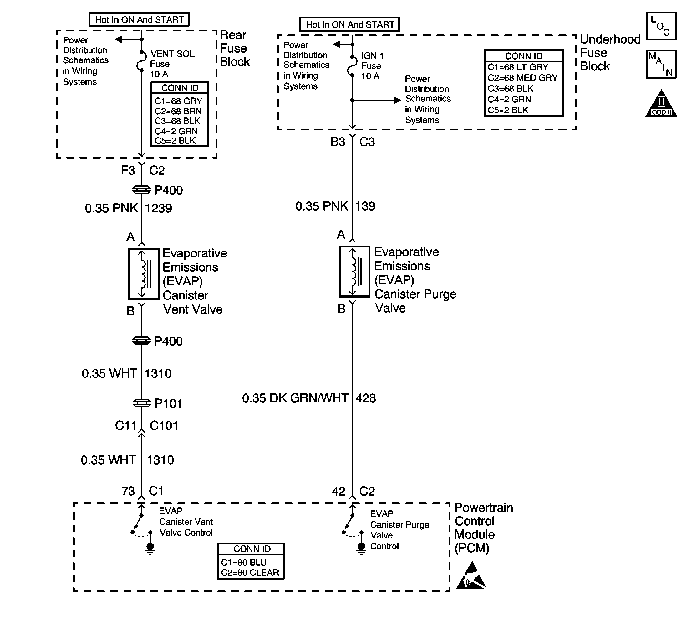
Circuit Description
The PCM uses output driver modules (ODMs) to control many functions of the engine, and the transaxle. The ODMs supply the ground path for the PCM controlled device when the PCM commands the device ON. Each ODM is able to control several outputs. Unlike the quad driver modules (QDMs) used in earlier model years, the ODMs are able to diagnose each output circuit. The PCM monitors the ODMs for circuit conditions that are incorrect for the commanded state of the ODM. If the PCM detects an improper circuit condition in the ODM that controls the EVAP purge solenoid valve, DTC P0443 will set.
Conditions for Running the DTC
| • | The engine is running. |
| • | The system voltage is between 8-16 volts. |
Conditions for Setting the DTC
| • | The PCM detects an improper voltage level on the output circuit that controls the EVAP purge solenoid valve. |
| • | The condition exists for at least 10 seconds. |
Action Taken When the DTC Sets
| • | The PCM illuminates the malfunction indicator lamp (MIL) during the second consecutive trip in which the diagnostic test runs and fails. |
| • | The PCM stores the conditions present when the DTC set as Freeze Frame/Failure Records data. |
Conditions for Clearing the MIL/DTC
| • | The PCM will turn the MIL OFF after the third consecutive trip in which the diagnostic runs and passes. |
| • | The history DTC will clear after 40 consecutive warm-up cycles have occurred without a malfunction. |
| • | The DTC can be cleared by using the scan tool Clear DTC Information function. |
Diagnostic Aids
To determine whether an improper voltage level exists on the output circuit, the PCM compares the voltage level to the commanded state. For example, a failure condition exists if the PCM detects a low voltage level when the device is commanded OFF, or a high voltage level when the device is commanded ON.
Check for the following conditions:
| • | Poor connections at the PCM or the EVAP purge solenoid valve. Refer to Testing for Intermittent Conditions and Poor Connections in Wiring Systems. |
| • | A damaged harness -- Inspect the wiring harness for damage. If the harness appears to be OK, disconnect the PCM and turn the ignition ON. Connect a digital multimeter (DMM) between the EVAP purge solenoid control circuit and chassis ground. Turn the ignition ON and observe the DMM while moving connectors and wiring harnesses related to the EVAP purge solenoid. A change in voltage will indicate the location of the malfunction. If a problem is found, repair as necessary. Refer to Wiring Repairs in Wiring Systems. |
Reviewing the Fail Records vehicle mileage since the diagnostic test last failed may assist in diagnosing the condition. The information may help in determining how often the condition that set the DTC occurs.
Test Description
The numbers below refer to the step numbers on the diagnostic table.
-
Listen for an audible click when the solenoid operates. Be sure that both the ON and the OFF states are commanded. Repeat the commands as necessary. The Fuel Tank Pressure sensor parameter on the scan tool can also be used to determine if the EVAP purge solenoid is operating. You should be able to see the pressure/vacuum change when you command the solenoid on.
-
This step tests for voltage at the EVAP purge solenoid. The ENG IGN fuse supplies power to the coil side of the EVAP purge solenoid.
-
This step verifies that the PCM is providing ground to the EVAP purge solenoid.
-
This step tests if a ground is constantly being applied to the EVAP purge solenoid.
Step | Action | Values | Yes | No |
|---|---|---|---|---|
1 | Did you perform the Powertrain On Board Diagnostic (OBD) System Check? | -- | ||
Does the solenoid respond to the commanded positions? | -- | |||
3 |
Does this DTC reset? | -- | Go to Intermittent Conditions | |
Does the test lamp illuminate? | -- | |||
Does the test lamp respond to each scan tool command? | -- | |||
Does the test lamp remain illuminated with each command? | -- | |||
7 |
Did you find and correct the condition? | -- | ||
8 |
Did you find and correct the condition? | -- | ||
9 |
Did you find and correct the condition? | -- | ||
10 |
Did you find and correct the condition? | -- | ||
11 | Repair the coil side feed circuit of the EVAP purge solenoid. Refer to Wiring Repairs in Wiring Systems. Is the action complete? | -- | -- | |
12 | Replace the solenoid. Refer to Evaporative Emission Canister Purge Solenoid Valve Replacement . Is the action complete? | -- | -- | |
13 |
Important: Program the replacement PCM. Replace the PCM. Refer to Powertrain Control Module Replacement/Programming . Is the action complete? | -- | -- | |
14 |
Does the DTC reset? | -- | ||
15 | With a scan tool, review the Stored information (capture info). Does the scan tool display any DTCs that you have not diagnosed? | -- | System OK |
