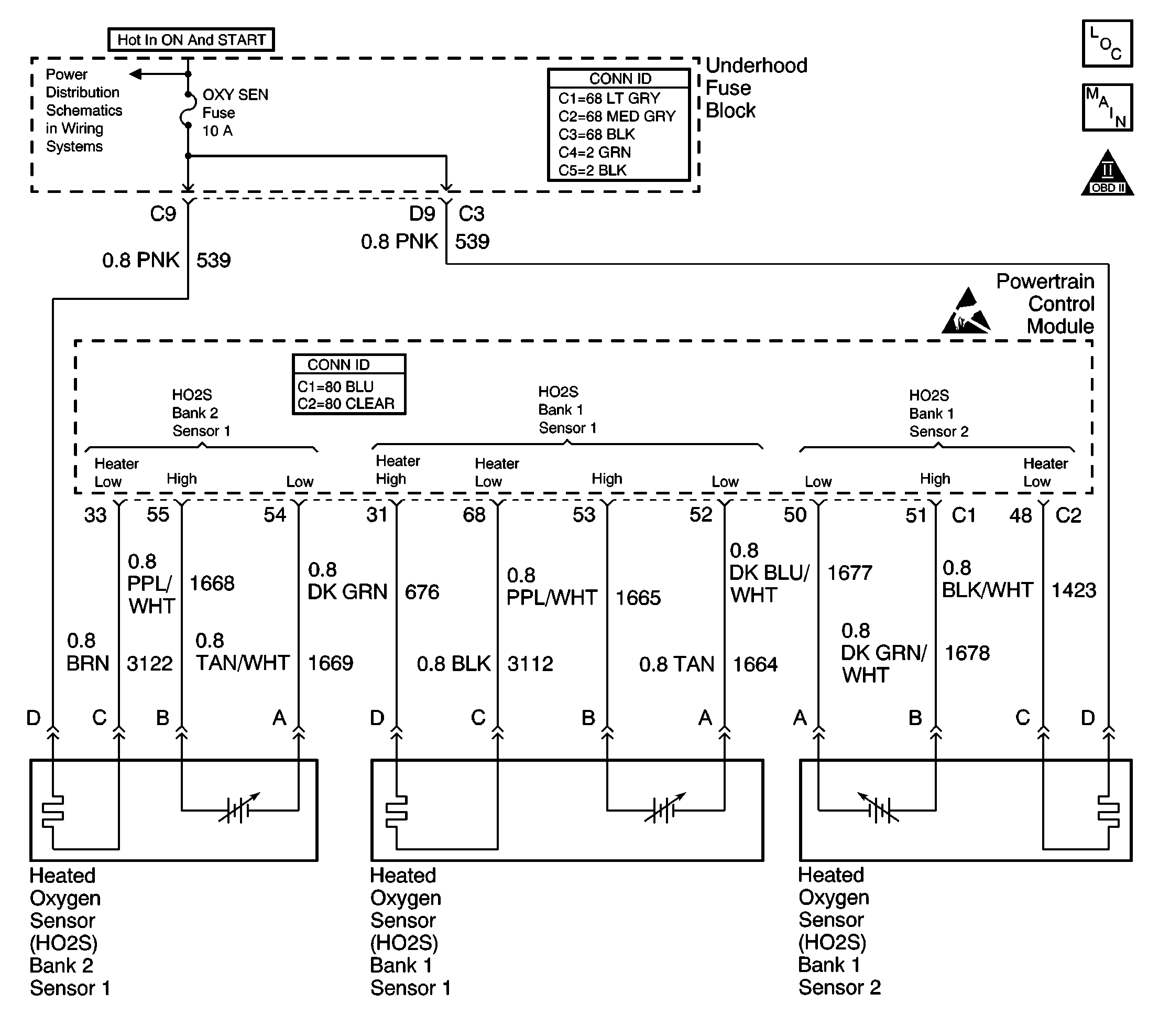
Circuit Description
The HO2S is a sensor used to detect oxygen-content in the exhaust. The PCM supplies the sensor with a signal circuit and a ground circuit. The PCM supplies a bias voltage between the circuits. The sensor varies the voltage based on the oxygen content in the exhaust. When the exhaust stream is lean (more oxygen), the sensor produces a low voltage signal. When the exhaust stream is rich (less oxygen), the sensor produces a high voltage signal. The PCM monitors the HO2S signal during closed loop. To correct for rich or lean conditions, the PCM adjusts the injector pulse width. If the signal frequency of HO2S bank 1 sensor 1 indicates an active sensor (closed loop), but the amplitude (voltage) of the signal remains within a calibrated range, DTC P0130 will set.
Conditions for Running the DTC
| • | TP sensor, MAF sensor, MAP sensor, IAT sensor, ECT sensor, fuel injector, or HO2S DTCs are not set. |
| • | Engine running more than 120 seconds (2 minutes). |
| • | System voltage is between 9 and 18 volts. |
| • | Predicted O2 heater temperature is more than 600°C (1112°F). |
| • | ECT is more than 75°C (167°F). |
| • | Traction control inactive. |
| • | Catalyst test is inactive. |
| • | Engine speed is between 500 and 5000 RPM. |
| • | MAF is between 3 g/s and 30.0 g/s. |
| • | Deceleration Fuel Cut Off (DFCO) is inactive. |
| • | Power Enrichment (PE) is inactive. |
| • | Conditions above met for 5 seconds. |
| • | Closed loop fuel control is enabled. |
Conditions for Setting the DTC
The vehicle is in closed loop fuel control, based on HO2S bank 1 sensor 1 and bank 2 sensor 1 voltages switching from below 350mV to above 500mV.
The PCM monitors the HO2S bank 2 sensor 1 voltage for 120 seconds (2 minutes).
During the 120 second monitoring period, the HO2S bank 2 sensor 1 voltage remains within 350 and 500 mV for approximately 16 seconds.
Action Taken When the DTC Sets
| • | The PCM illuminates the malfunction indicator lamp (MIL) during the second consecutive trip in which the diagnostic test runs and fails. |
| • | The PCM stores the conditions present when the DTC set as Freeze Frame/Failure Records data. |
Conditions for Clearing the MIL/DTC
| • | The PCM will turn the MIL OFF after the third consecutive trip in which the diagnostic runs and passes. |
| • | The history DTC will clear after 40 consecutive warm-up cycles have occurred without a malfunction. |
| • | The DTC can be cleared by using the scan tool Clear DTC Information function. |
Diagnostic Aids
If the problem is intermittent, refer to Intermittent Conditions .
Step | Action | Values | Yes | No | ||||||
|---|---|---|---|---|---|---|---|---|---|---|
1 | Did you perform the Powertrain On Board Diagnostic (OBD) System Check? | -- | ||||||||
2 |
Does the scan tool indicate HO2S bank 1 sensor 1 voltage varying outside the specified values? | 350-500 mV | ||||||||
3 |
Does the scan tool indicate DTC P0130 failed last test? | -- | Go to Diagnostic Aids | |||||||
4 |
Does the scan tool indicate an HO2S bank 1 sensor 1 voltage below the specified value? | 150 mV | ||||||||
5 |
Did you find and correct the condition? | -- | ||||||||
6 |
Did you find and correct the condition? | -- | ||||||||
7 | Replace HO2S bank 1 sensor 1. Refer to Heated Oxygen Sensor Replacement - Bank 1 Sensor 1 Is the action complete? | -- | -- | |||||||
8 |
Important:: The replacement PCM must be programmed. Replace the PCM. Refer to Powertrain Control Module Replacement/Programming . Is the action complete? | -- | -- | |||||||
9 |
Does the scan tool indicate DTC P0130 passed? | -- | System OK |
