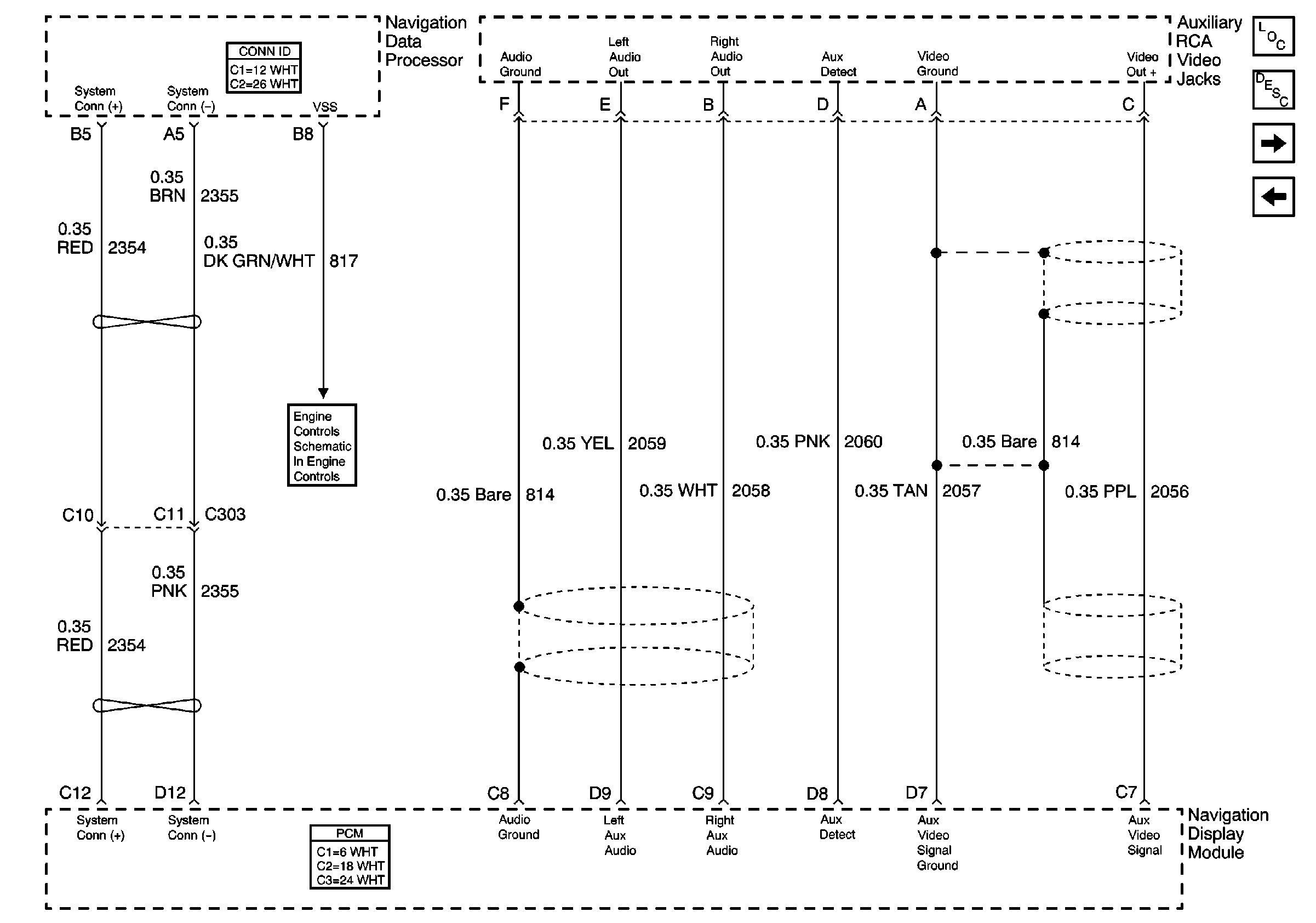
Refer to
Auxiliary RCA Video Jacks

Circuit Description
The navigation display head (NDH) communicates with the navigation module (NAV) over two dedicated lines. These are the navigation display serial data high circuit and the navigation display serial data low circuit.
Conditions for Running the DTC
The navigation display head (NDH) must detect a power mode transition from the OFF-ASLEEP state to one of the following:
| • | ACC |
| • | ON |
The navigation display head (NDH) does not set this DTC if B1327 or B1328 is current.
Conditions for Setting the DTC
There is no response from the NAV when queried by the NDH.
The NDH does not receive a command from the NAV after 15 seconds.
Action Taken When the DTC Sets
The display does not update or change functions or the screen may become blank.
The message LOSS OF COMMUNICATION WITH NAVIGATION PROCESSOR may appear on the display.
Conditions for Clearing the DTC
The NDH receives a response from the NAV.
Diagnostic Aids
Test for intermittent shorts and opens on the navigation display serial data high circuit and the navigation display serial data low circuit.
Test for intermittent shorts and opens on the navigation module (NAV) supply and ground circuits.
Refer to Testing for Electrical Intermittents in Wiring Systems.
Step | Action | Value(s) | Yes | No | ||||
|---|---|---|---|---|---|---|---|---|
1 | Did you perform Diagnostic System Check - Navigation System ? | -- | Go to Step 2 | |||||
2 |
Important:: The communications circuits will not be at a constant steady voltage level.
Ignoring polarity, is each voltage within the range specified? | 2.0-3.0 V | Go to Step 5 | Go to Step 3 | ||||
3 | Test the following circuits for all shorts and opens:
Refer to Circuit Testing and Wiring Repairs in Wiring Systems. Did you find and correct the condition? | -- | Go to Step 8 | Go to Step 4 | ||||
4 | Inspect for poor connections at the harness connector of the navigation module (NAV). Refer to Testing for Intermittent Conditions and Poor Connections and Connector Repairs in Wiring Systems. Did you find and correct the condition? | -- | Go to Step 8 | Go to Step 5 | ||||
5 | Replace the navigation module (NAV). Refer to Navigation Data Processor Replacement in Entertainment. Did you complete the replacement? | -- | Go to Step 8 | -- | ||||
6 | Inspect for poor connections at the harness connector of the navigation display head (NDH). Refer to Testing for Intermittent Conditions and Poor Connections and Connector Repairs in Wiring Systems. Did you find and correct the condition? | -- | Go to Step 8 | Go to Step 7 | ||||
7 | Replace the navigation display head (NDH). Refer to Navigation Display Module Replacement in Entertainment. Did you complete the replacement? | -- | Go to Step 8 | -- | ||||
8 |
Does the DTC reset? | -- | Go to Step 2 | System OK |
