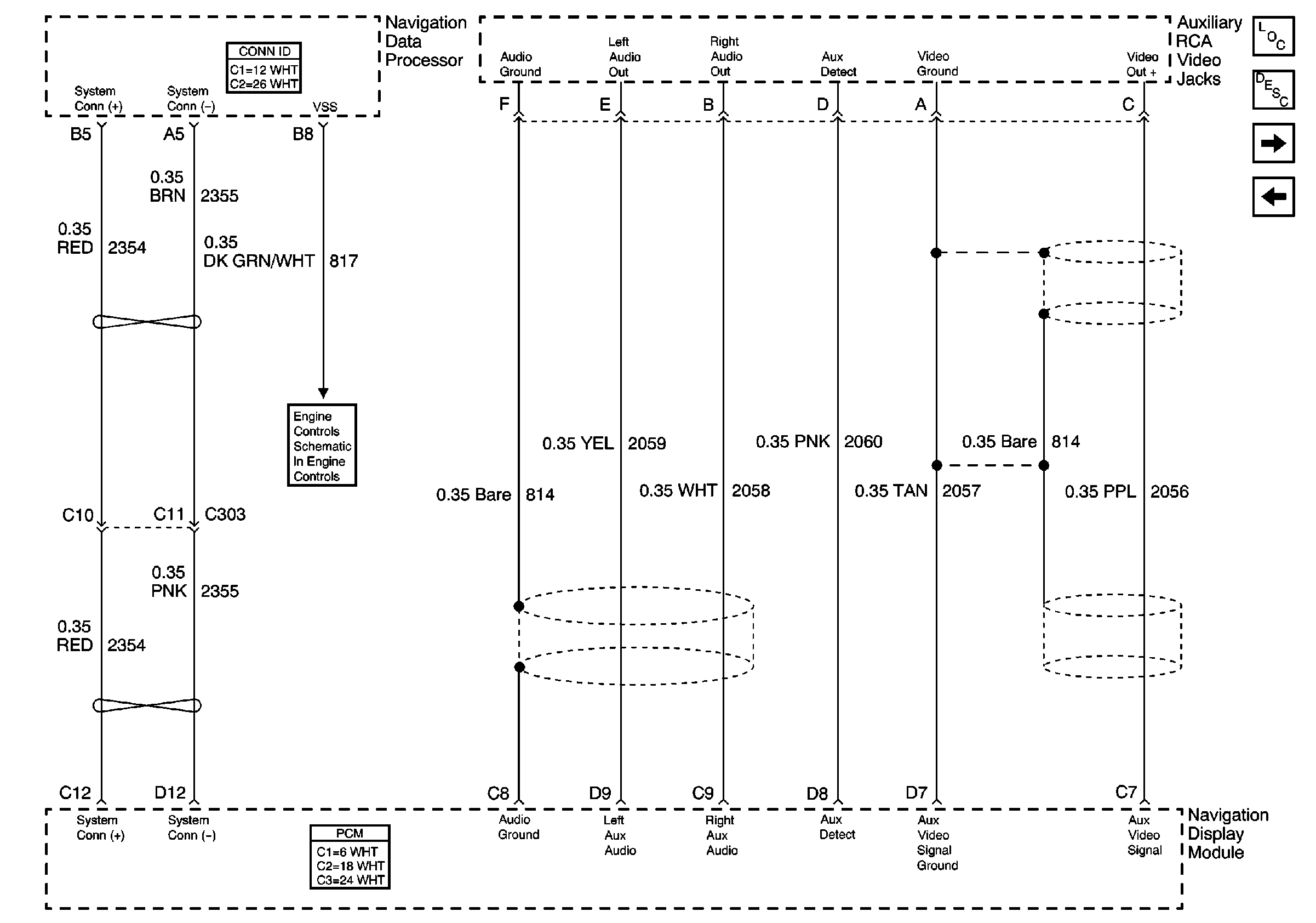
Refer to
Auxiliary RCA Video Jacks

Circuit Description
The navigation module (NAV) receives the VSS signal from the PCM through a dedicated circuit shared with the instrument cluster.
Conditions for Running the DTC
The navigation module (NAV) must detect a power mode transition to ON.
The NAV does not set this DTC if B1327 or B1328 is current.
The vehicle must drive for 2.5 miles after receiving a GPS signal. The receipt of the GPS signal is indicated by an icon (box) in the upper left quadrant of the map screen with the letters GPS inside of it.
Conditions for Setting the DTC
The navigation module (NAV) compares the VSS signal from the PCM to the GPS location signal every second. If the GPS signal indicates that the vehicle has traveled 2.5 miles but no VSS signal was received, the NAV sets the DTC.
Action Taken When the DTC Sets
The navigation module (NAV) uses the GPS signal when the VSS signal from the PCM is unavailable.
The following symptoms may happen if the VSS signal from the PCM is unavailable:
| • | The vehicle icon may jump to different positions on the map screen. |
| • | The vehicle icon may not move on the map screen while the vehicle is being driven. |
| • | The route guidance accuracy may be degraded. |
Conditions for Clearing the DTC
| • | A current DTC clears when the navigation module (NAV) detects the VSS signal from the PCM for more than one second. |
| • | A history DTC clears after 50 ignition cycles without a VSS signal failure. |
Diagnostic Aids
An intermittent condition may be caused by the following:
| • | Mis-routed harness |
| • | Rubbed through wire insulation |
| • | Broken wire inside the insulation |
| • | A loose connector pin |
Test Description
The number(s) below refer to the step number(s) on the diagnostic table.
-
Determines if the malfunction is present.
-
Tests for an open in the VSS signal circuit between the instrument cluster and the navigation module (NAV). A short would cause the instrument cluster to malfunction as well as the navigation system.
Step | Action | Yes | No |
|---|---|---|---|
Did you perform Diagnostic System Check - Navigation System ? | |||
2 | Verify the instrument cluster speedometer operation. Does the speedometer work on the instrument cluster? | ||
Test the VSS signal circuit for an open between the instrument cluster and the navigation module (NAV). Refer to Circuit Testing and Wiring Repairs in Wiring Systems. Did you find and correct the condition? | |||
4 | Inspect for poor connections at the harness connector of the navigation module (NAV). Refer to Testing for Intermittent Conditions and Poor Connections and Connector Repairs in Wiring Systems. Did you find and correct the condition? | ||
5 | Replace the navigation module (NAV). Refer to Navigation Data Processor Replacement in Entertainment. Did you complete the replacement? | -- | |
6 |
Does the DTC reset? | System OK |
