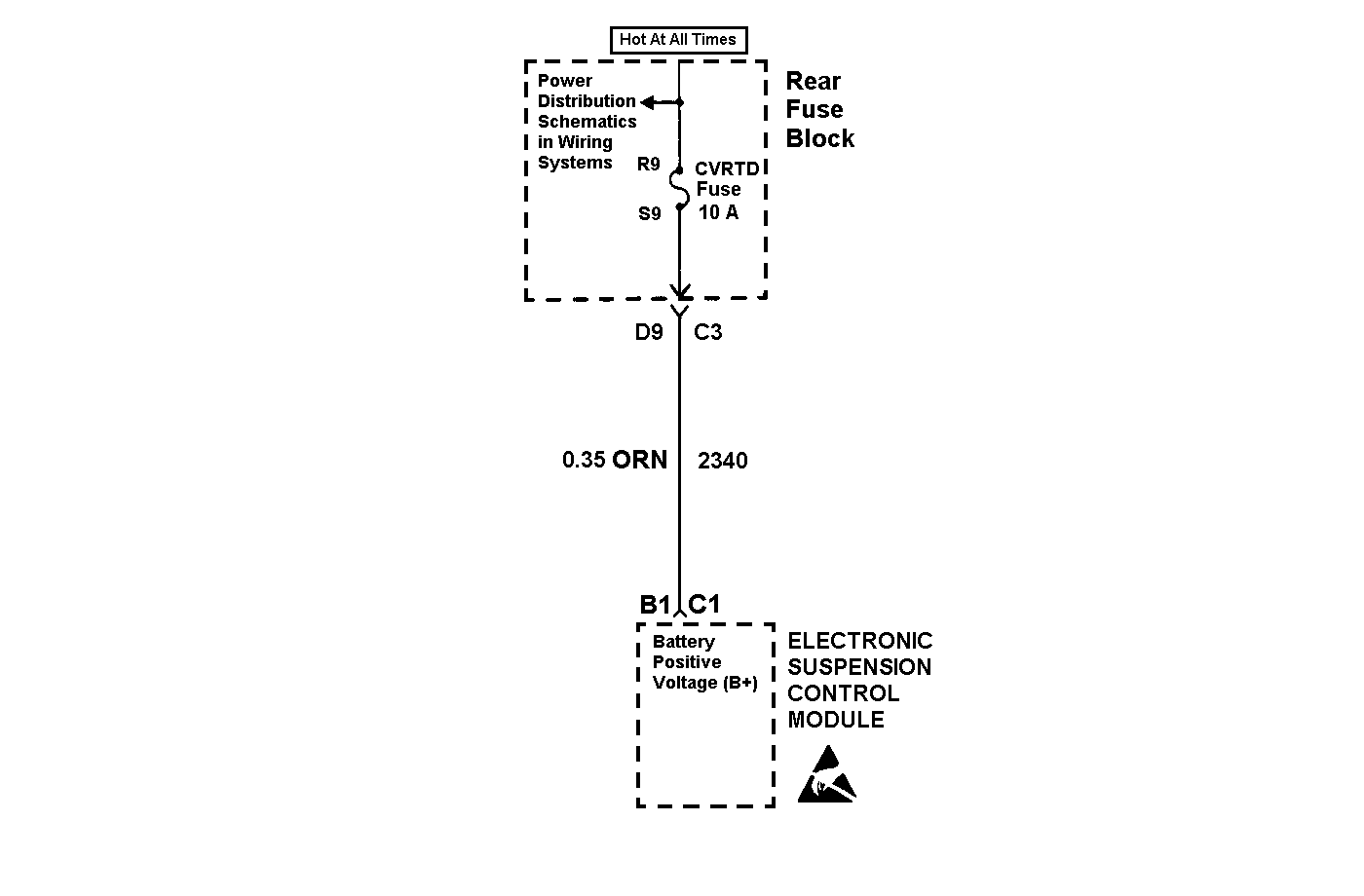
Circuit Description
Battery voltage is supplied to the Electronic Suspension Control module at connector C1, terminal B1. The Electronic Suspension Control module monitors the supplied battery voltage to determine if it is within a valid operating range.
Conditions for Running the DTC
| • | The ignition is on. |
| • | The fault is detected during three consecutive ignition cycles, or during the same ignition cycle after clearing the DTC with the scan tool. |
Conditions for Setting the DTC
The DTC is set when the battery voltage is outside the normal range of 9 to 15.5 volts.
Action Taken When the DTC Sets
DTC C0896 disables the ability to set most other CVRSS DTCs.
Conditions for Clearing the MIL/DTC
| • | The scan tool can be used to clear the DTC. |
| • | The On-Board diagnostic CLEAR RSS CODES feature can be used to clear the DTC. |
| • | The DTC is saved as history when the Electronic Suspension Control module no longer sees battery voltage outside the normal range of 9 to 15.5 volts. The DTC will clear if the fault does not return after 50 consecutive ignition cycles. |
Diagnostic Aids
DTC C0896 may set when the vehicle is placed on a battery charger, on fast charge, for a long period of time. It may also be set by an intermittent charging system malfunction.
Test Description
The number(s) below refer to the step number(s) on the diagnostic table.
Step | Action | Value(s) | Yes | No |
|---|---|---|---|---|
Measure the voltage in the Electronic Suspension Control module battery positive voltage circuit. Does the voltage the measure within the specified values? | 9-15.5 V | Go to Step 3 | Go to Step 2 | |
2 | Test for high resistance, a short to ground or an open in the battery positive voltage circuit of the Electronic Suspension Control module. Refer to Circuit Testing and Wiring Repairs in Wiring Systems. Did you find and correct the condition? | -- | Go to Step 7 | |
3 |
Does the DTC reset? | -- | Go to Step 4 | Go to Step 6 |
4 | Inspect for poor connections at the harness connector of the Electronic Suspension Control module. Refer to Testing for Intermittent Conditions and Poor Connections and Connector Repairs in Wiring Systems. Did you find and correct the condition? | -- | Go to Step 7 | Go to Step 5 |
5 |
Important: Perform the set up and calibration procedure for the Electronic Suspension Control module. Replace the Electronic Suspension Control module. Refer to Electronic Suspension Control Module Replacement . Did you complete the replacement? | -- | Go to Step 7 | -- |
6 | Inspect for poor connections at the harness connector of the Electronic Suspension Control module. Refer to Testing for Intermittent Conditions and Poor Connections and Connector Repairs in Wiring Systems. Did you find and correct the condition? | -- | Go to Step 7 | Go to Diagnostic Aids |
7 |
Does the DTC reset? | -- | Go to Step 2 | System OK |
