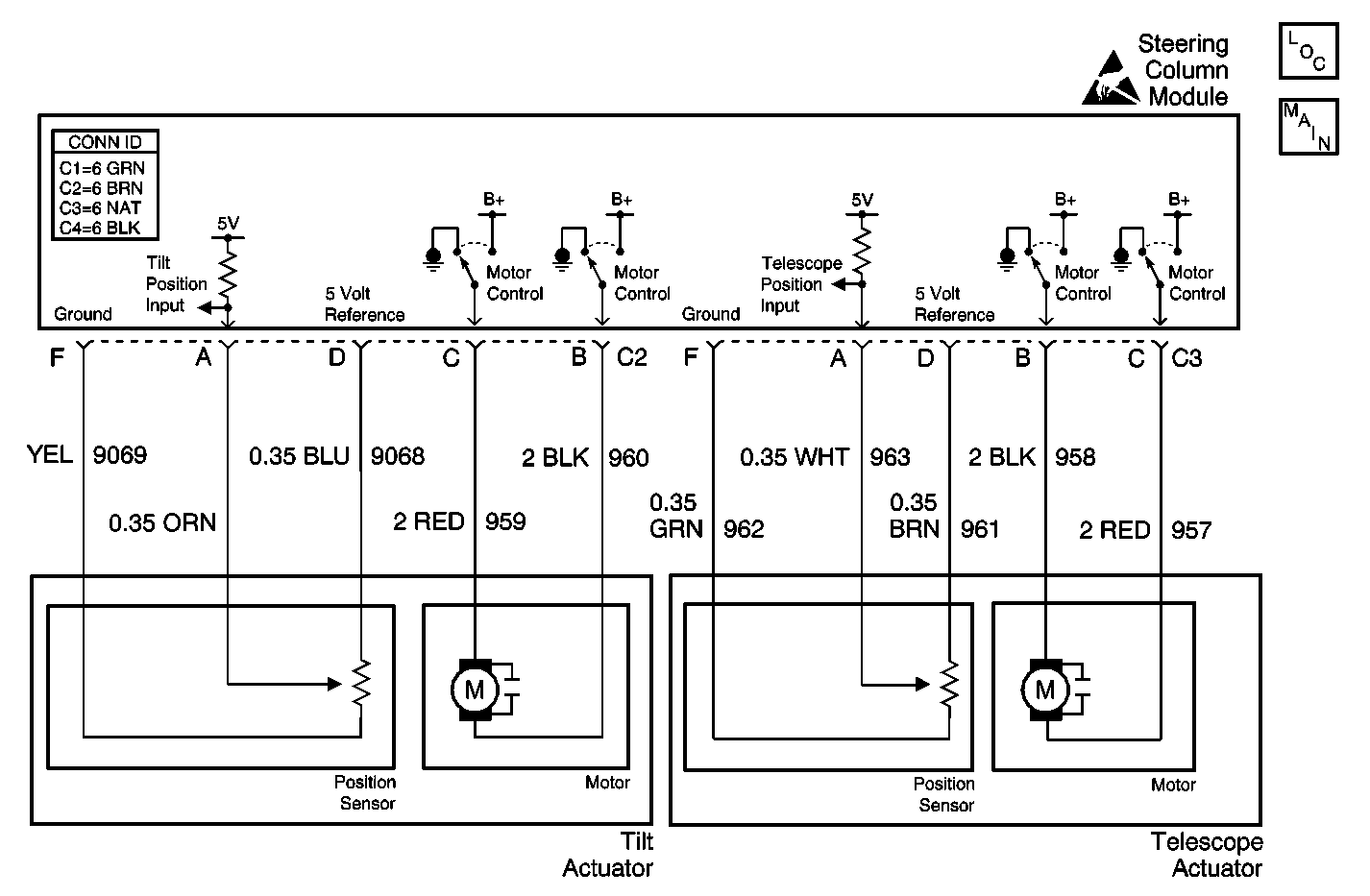
Circuit Description
The steering column module receives ground inputs from contacts inside the tilt/telescoping switch. The steering column module then supplies battery voltage to the tilt motor UP or DOWN circuit, or, the telescope motor IN or OUT circuit depending on which direction of movement is requested. Both motors are reversible and the circuits are simply reversed to accomplish movement in opposite directions.
Conditions for Running the DTC
DTC B1327 is not set as current.
Conditions for Setting the DTC
This DTC will set as current when the motor current is greater than 7 amps for 100 milliseconds.
Action Taken When the DTC Sets
The steering column module enables the affected motor for manual and memory recall positioning. A reoccurrence of the over current condition causes the affected motor to stop.
Conditions for Clearing the DTC
| • | This DTC will clear from current status when the motor current is less than 7 amps for 100 milliseconds. |
| • | Use the On-Boards clearing DTCs feature. |
| • | Use a scan tool. |
Diagnostic Aids
Since most occurrences of this DTC may caused by excessive current during cold weather conditions, review the circumstances with the customer to verify the conditions under which the DTC set.
Step | Action | Value(s) | Yes | No |
|---|---|---|---|---|
1 | Did you perform the Tilt/Telescoping Steering Column Diagnostic System Check? | -- | Go to Step 2 | Go to Tilt/Telescoping Steering Column Diagnostic System Check |
2 |
Does the Motor Current parameter display more than the specified value? | 7 amps | Go to Step 4 | Go to Step 3 |
3 | With the scan tool, observe the Motor Current parameter while operating the switch from the Idle position to the In and Out positions. Does the Motor Current parameter display more than the specified value? | 7 amps | Go to Step 5 | Go to Diagnostic Aids |
4 |
Important:: Perform the set up procedure for the steering column module. Replace the tilt actuator. Refer to Tilt Actuator Assembly Replacement - On Vehicle . Did you complete the replacement? | -- | Go to Step 6 | -- |
5 |
Important:: Perform the set up procedure for the steering column module. Replace the telescope actuator. Refer to Telescope Actuator Assembly Replacement - On Vehicle . Did you complete the replacement? | -- | Go to Step 6 | -- |
6 |
Does the DTC reset? | -- | Go to Step 2 | System OK |
