Valve Stem Oil Seal and Valve Spring Replacement Intake
Removal Procedure
Tools Required
| • | J 36588 Valve
Spring Compressor T-bolt |
| • | J 36011 Spark
Plug Connector Assembly Remover |
Caution: Unless directed otherwise, the ignition and start switch must be in the OFF or LOCK position, and all electrical loads must be OFF before servicing
any electrical component. Disconnect the negative battery cable to prevent an electrical spark should a tool or equipment come in contact with an exposed electrical terminal. Failure to follow these precautions may result in personal injury and/or damage to
the vehicle or its components.
Important: If you loosen or remove the bolts which secure the camshaft housing
to the cylinder head, replace the gasket between the camshaft housing and
the cylinder head.
- Disconnect the negative battery cable.
- Disconnect the ignition coil and module assembly electrical connections.
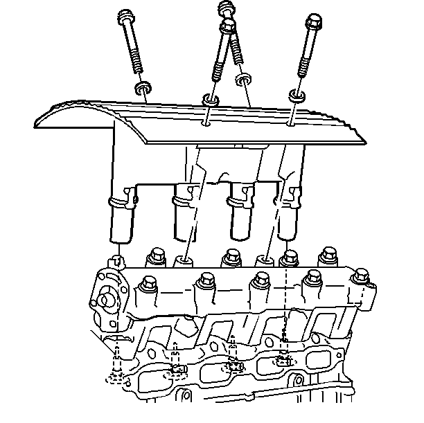
- Remove the ignition coil
and the bolts which secure the module assembly to the camshaft housing.
- Remove the assembly by pulling straight up.
- If the connector assembly is stuck to the spark plugs, use J 36011
in order to remove the
connector assembly. First twist and then pull up on the connector assembly.
- Disconnect the electrical connection from the oil pressure switch.
- Disconnect the timing chain housing at the exhaust camshaft housing,
but do NOT remove the housing from the vehicle. Refer to
Timing Chain Housing Replacement
.
Notice: Turn the camshaft housing upside down as soon as it is removed from
the cylinder head. The lifters will fall out of the camshaft housing if it
is not turned upside down. the lifters can be damaged if they
fall out and hit a hard surface.
Important: Use the reverse of the tightening procedure when loosening the retaining
bolts which secure the camshaft housing to the cylinder head.
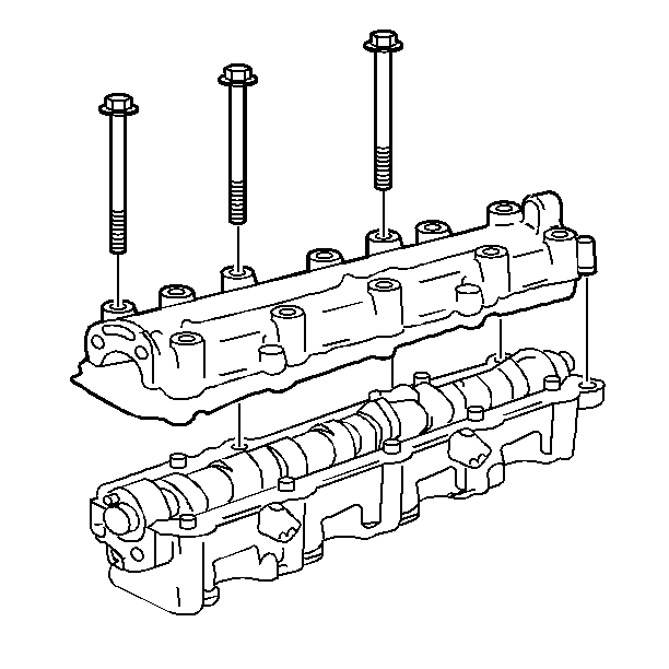
- Remove the bolts which
secure the exhaust camshaft housing to the cylinder head.
- Remove the exhaust camshaft housing.
- Remove the camshaft housing gasket.
- Remove the spark plug.
- Using a suitable adapter, apply air pressure to the cylinder.
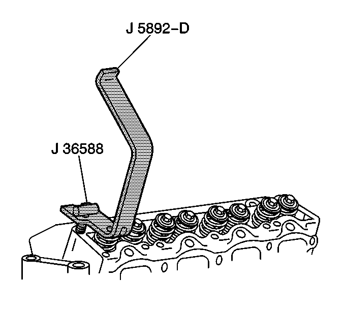
- Compress the valve spring.
Use the J 5892-D
and the J 36588
.
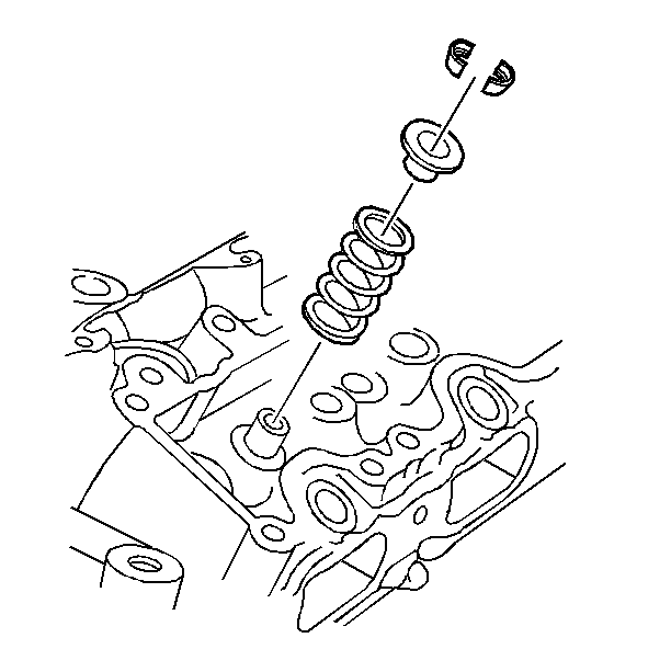
- Disassemble the following
components:

- Disassemble the following
components:
| • | The valve spring seat (exhaust) |

Assemble the rotator (intake).
- Assemble the valve spring seat (exhaust).
- Install a new, clean and dry valve seal. Push the seal on by hand
in order to seat the seal fully.

- Install the spring and
retainer. Use the J 36588
,
and the J 5892-D
in order
to compress the valve spring.
- The valve keys
- Inspect for proper valve key seating.
Installation Procedure
- Remove the air line adapter.
- Install the spark plug.
Notice: Carefully roll the camshaft housing right side up as it is installed
onto the cylinder head. The lifters can be damaged if they fall
out and hit a hard surface.
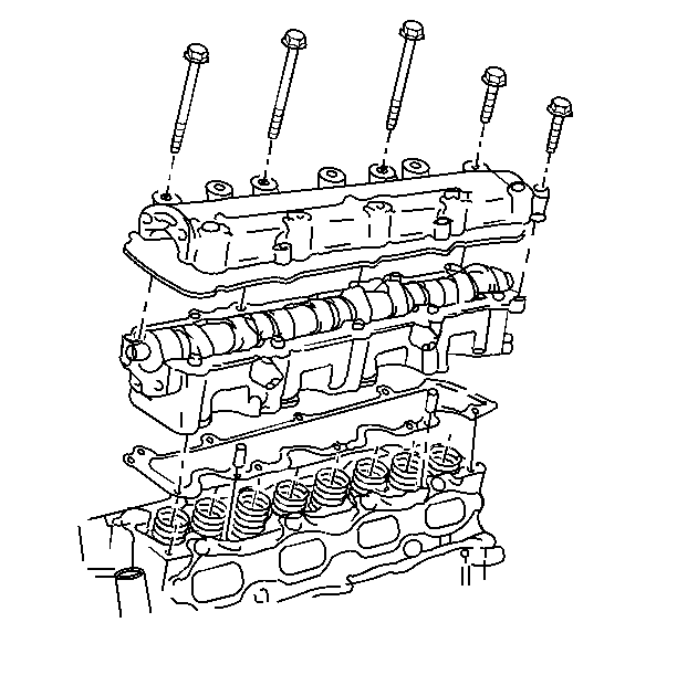
- Install the exhaust camshaft
housing.
- Apply pipe sealant GM P/N 1052080 or equivalent to the
threads of the camshaft housing retaining bolt.
Notice: Use the correct fastener in the correct location. Replacement fasteners
must be the correct part number for that application. Fasteners requiring
replacement or fasteners requiring the use of thread locking compound or sealant
are identified in the service procedure. Do not use paints, lubricants, or
corrosion inhibitors on fasteners or fastener joint surfaces unless specified.
These coatings affect fastener torque and joint clamping force and may damage
the fastener. Use the correct tightening sequence and specifications when
installing fasteners in order to avoid damage to parts and systems.
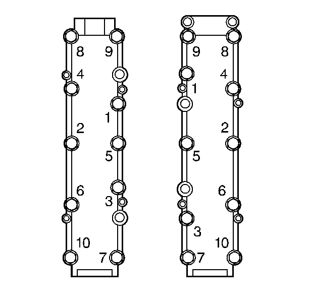
- Use the J 36660-A
in order to install the bolts. Install
the bolts in sequence.
Tighten
Tighten the bolts to 14 N·m (124 lb in).
- Install the timing chain housing to the camshaft housing and timing
chain. Refer to
Timing Chain Housing Replacement
.
- Connect the electrical connection to the oil pressure switch.
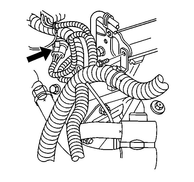
- If any spark plug boot
connector assembly has stuck to a spark plug, reinstall the connector onto
the ignition coil and the module assembly.
- Place the ignition coil and module assembly over the spark plugs
and push straight down.

- Clean any lubricant that
is present on the ignition coil and on the bolts which secure the module assembly
to the camshaft housing.
- Apply Pipe Sealant GM P/N 1052080 or equivalent onto the
ignition coil and onto the bolts which secure the module assembly to the camshaft
housing.
- Install the ignition coil and install the bolts which secure the
module assembly to the camshaft housing.
Tighten
Tighten the bolts to 15 N·m (11 lb ft) +
30 degrees.

- Connect the electrical
connector to the ignition coil and to the module assembly.
- Connect the negative battery cable.
Valve Stem Oil Seal and Valve Spring Replacement Exhaust
Removal Procedure
Tools Required
| • | J 36588 Valve
Spring Compressor T-Bolt |
| • | J 36011 Spark
Plug Connector Assembly Remover |
Important: Any time the camshaft housing to the cylinder head bolts are loosened
or removed, the camshaft housing to the cylinder head gasket must be replaced.
Caution: Unless directed otherwise, the ignition and start switch must be in the OFF or LOCK position, and all electrical loads must be OFF before servicing
any electrical component. Disconnect the negative battery cable to prevent an electrical spark should a tool or equipment come in contact with an exposed electrical terminal. Failure to follow these precautions may result in personal injury and/or damage to
the vehicle or its components.
- Disconnect
the negative battery cable.
- Disconnect the ignition coil and module assembly electrical connections.

- Remove the ignition coil
and module assembly to the camshaft housing bolts.
- Remove the assembly by pulling straight up.
- Use the J 36011
in
order to remove the connector assembly if the connector assembly is stuck
to the spark plugs.
- Use the tool by first twisting then pulling up on the connector
assembly.
- Disconnect the electrical connection from the oil pressure switch.
- Disconnect the timing chain housing at the exhaust camshaft housing,
but do not remove it from the vehicle. Refer to
Timing Chain Housing Replacement
.
Notice: Turn the camshaft housing upside down as soon as it is removed from
the cylinder head. The lifters will fall out of the camshaft housing if it
is not turned upside down. the lifters can be damaged if they
fall out and hit a hard surface.
Important: Use the reverse of the tightening procedure when loosening the camshaft
housing to the cylinder head retaining bolts.

- Remove the exhaust camshaft
housing to the cylinder head bolts.
- Remove the exhaust camshaft housing.
- Remove the camshaft housing gasket.
- Remove the spark plug.
- Using a suitable adapter, apply air pressure to the cylinder.

- Compress the valve spring.
Use the J 5892-D
and the J 36588
.

- Disassemble the following
components:
| • | The valve spring seat (exhaust) |
- Assemble the following components:
| • | The valve spring seat (exhaust) |
| • | A new, clean and dry valve seal. Push the seal on by hand in order
to ensure that the seal is fully seated. |
| • | The spring and retainer. Use the J 36588
, and the J 5892-D
in order to compress the valve spring. |
- Inspect for proper valve key seating.
Installation Procedure
- Remove the air line adapter.
- Install the spark plug.
Notice: Carefully roll the camshaft housing right side up as it is installed
onto the cylinder head. The lifters can be damaged if they fall
out and hit a hard surface.

- Install the exhaust camshaft
housing.
- Apply Pipe Sealant GM P/N 1052080 or equivalent to the
camshaft housing retaining bolt threads.

Notice: Use the correct fastener in the correct location. Replacement fasteners
must be the correct part number for that application. Fasteners requiring
replacement or fasteners requiring the use of thread locking compound or sealant
are identified in the service procedure. Do not use paints, lubricants, or
corrosion inhibitors on fasteners or fastener joint surfaces unless specified.
These coatings affect fastener torque and joint clamping force and may damage
the fastener. Use the correct tightening sequence and specifications when
installing fasteners in order to avoid damage to parts and systems.
- Use the J 36660-A
in order to install the bolts. Install
the bolts in sequence.
Tighten
Tighten the bolts to 14 N·m (124 lb in).
- Install the timing chain housing to the camshaft housing and timing
chain. Refer to
Timing Chain Housing Replacement
.
- Connect the electrical connection to the oil pressure switch.
- Reinstall any spark plug boot connector assembly that stuck to
a spark plug, back onto the ignition coil and module assembly.
- Place the ignition coil and module assembly over the spark plugs
and push straight down.

- Clean any lubricant that
is present on the ignition coil and module assembly to the camshaft housing
bolts.
- Apply Pipe Sealant GM P/N 1052080 or equivalent onto the
ignition coil and module assembly to the camshaft housing bolts.
- Install the ignition coil and module assembly to the camshaft
housing bolts.
Tighten
Tighten the bolts to 15 N·m (11 lb ft) +30 degrees.
- Connect the electrical connector to the ignition coil and module
assembly.
- Connect the negative battery cable.


