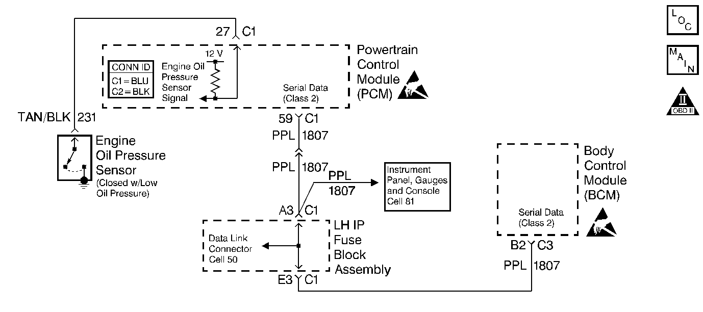
Diagnosis
| • | The following table will diagnose the oil pressure switch. |
| • | For diagnosis of the Body Control Module (BCM), refer to Body Control Module System Check in Body Control Systems. |
| • | Replacement PCMs must be reprogrammed and the crankshaft position system variation procedure must be performed. Refer to the latest Techline information for PCM programming and the Crankshaft Position System Variation Learn Procedure. |
Circuit Description
The scan tool displays oil pressure as Low or OK.
The PCM checks the engine oil pressure continuously. If the oil pressure switch indicates low oil pressure at any time, the PCM will send information through serial data to the Body Control Module (BCM) to turn ON the Low Oil Pressure telltale located on the Instrument Panel Cluster (IPC). If the engine oil pressure drops below approximately 13.8 kPa. (2 psi.) when the engine is running, the Low Oil Pressure telltale will illuminate.
Diagnostic Aids
| • | Low oil level or low oil pressure at times may be caused by an engine mechanical problem. If a low oil pressure problem is suspected, refer to the Oil Pressure Diagnosis and Testing in Engine Mechanical. |
| • | An Intermittent problem may be caused by the following conditions: |
| - | Poor electrical connection |
| - | Rubbed through wire insulation |
| - | A wire that is broken inside the insulation |
| • | Any circuitry, that is suspected as causing the intermittent complaint, should be thoroughly checked for the following conditions: |
| - | Backed out terminals |
| - | Improper mating |
| - | Broken locks |
| - | Damage to the wiring harness |
Test Description
The numbers below refer to the step numbers on the Diagnostic Table.
-
The Powertrain OBD System Check prompts you to complete some of the basic checks and to store the freeze frame and failure records data on the scan tool if applicable. This creates an electronic copy of the data captured when the malfunction occurred. The scan tool stores this information for later reference.
-
This step is crucial to preventing possible engine damage due to a low oil condition.
-
The PCM senses when the oil pressure signal is pulled low by the oil pressure switch. This step will determine if the PCM is able to sense the signal.
-
When the oil pressure is low, the signal circuit is grounded through the oil pressure switch. This step will determine if the signal is grounded because of the oil pressure switch or a short to ground.
-
The PCM uses a voltage signal to sense when the oil pressure circuit is pulled low. This step will determine if battery voltage was on this circuit normally or because of a short. When the signal circuit is probed by a test light connected to ground, the oil pressure symbol will illuminate.
-
If an oil pressure problem is suspected, do not run the engine longer than necessary to avoid possible internal engine damage.
-
Refer to the Body Control Module System Check in Body Control Systems for BCM diagnosis.
-
Reprogram the replacement PCM and perform the crankshaft position system variation learning procedure. Refer to the latest Techline information for PCM programming and the Crankshaft Position System Variation Learn for the crankshaft position system variation learn procedure.
-
If no malfunctions have been found at this point, refer to Diagnostic Aids for additional checks and information.
Step | Action | Value(s) | Yes | No | ||||
|---|---|---|---|---|---|---|---|---|
Did you perform the Powertrain On-Board Diagnostic (OBD) System Check? | -- | |||||||
Check the engine oil level. Is the engine oil level OK? | -- | |||||||
3 |
Was a DTC U1000 or U1064 set? | -- | Go to Applicable DTC Table | |||||
4 | Does the engine oil pressure telltale lamp illuminate and stay illuminated? | -- | ||||||
5 | Add engine oil. Is the action complete? | -- | -- | |||||
6 | Start the engine. Is the oil pressure telltale lamp illuminated? | -- | ||||||
Does the DMM read the specified value? | B+ | |||||||
Does the test light illuminate? | -- | |||||||
Does the test light illuminate? | -- | |||||||
10 |
Was a repair necessary? | -- | ||||||
11 |
Was a repair necessary? | -- | ||||||
12 |
Does the scan tool indicate low oil pressure? | -- | ||||||
13 |
Does the scan tool indicate low oil pressure? | -- | ||||||
14 |
Was a repair necessary? | -- | ||||||
Was a repair necessary? | -- | |||||||
Refer to Body Control Module System Check in Body Control Systems for further diagnosis. Is the action complete? | -- | -- | ||||||
17 |
Was a repair necessary? | -- | ||||||
18 |
Caution: Avoid contact with moving parts and hot surfaces while working around a running engine in order to prevent physical injury. Replace the engine oil pressure switch. Is the action complete? | -- | -- | |||||
Replace the PCM. Refer to the Powertrain Control Module Replacement for the replacement procedure. Is the action complete? | -- | -- | ||||||
Operate the vehicle within the conditions under which the original symptom was observed. Does the system now operate properly? | -- | System OK |
