No Start In High Electromagnetic Interference Areas (Retrofit Vehicle to Use PASS-Key III Theft Deterrent System)

| Subject: | No Start in High Electromagnetic Interference Areas (Retrofit Vehicle to Use PASS-Key®III Theft Deterrent System) |
| Models: | 1999-2000 Chevrolet Alero |
| Attention: | This bulletin is for use in Europe, Russia and Israel only. US and Canadian dealers are not authorized to use this bulletin. |
Condition
Some customers may comment that they were unable to start the vehicle at the airport (or other areas with high electromagnetic and/or microwave interference (EMI)).
Cause
EMI may be blocking the Passlock™ signal to the module and causing the no start condition.
Correction
- Locate the key cylinder, P/N 22672292, in the retrofit kit.
- Remove all components from the part box.
- Separate the black collar from the lock cylinder housing by gently lifting the locking tab and sliding the assembly from the lock cylinder housing.
- Remove the lock cylinder from the lock cylinder housing.
- Gently place the light pipe (the clear plastic ring) into the lock cylinder bezel (the black and grey piece) from the front. If they do not go together easily, it may be necessary to polish the bezel with fine sandpaper so they will fit together easily.
- Place the light pipe into the back side of the bezel, aligning the wide spaces. Use the lock cylinder to press them together. Do not force. If they do not seat together easily, damage to the bezel and or light pipe will occur.
- Assemble the springs and tumblers into the lock cylinder to match the original customer keys.
- With the customer's original key in the lock cylinder, verify that all the tumblers are flush with the lock cylinder assembly. If they are not, the offending tumbler is incorrect. Redo that tumbler.
- With the key in the lock cylinder, place the lock cylinder assembly into the lock cylinder housing. The lock cylinder must rotate easily in the housing.
- Remove the key.
- Cut one of the new keys, P/N 22672534, to match the customer's original key.
- Does the newly-cut key turn the lock cylinder? If not, the key was improperly cut.
- Repeat the last two steps for the remaining keys.
- Remove the key from the lock cylinder.
- Place the PASS-Key® (black) collar assembly back onto the lock cylinder housing assembly. Ensure the locking tab is locked.
- Disconnect the negative battery cable from the battery.
- Remove the right side instrument panel closeout to gain access to the Body Control Module (BCM).
- For improved access, disconnect the courtesy lamp from its attachment point and let hang.
- Disconnect the wiring harnesses from the BCM and remove the BCM from the vehicle. Discard the BCM. It will not be reused.
- Locate the BCM 24-way grey connector (C2) and remove two wires from the connector. The wires in cavities A6 (a black wire) and the wire in B6 (a yellow wire) are to be removed from the connector body and taped back to the wiring harness or cut off as close to the harness as possible.
- Locate the BCM 24-way pink connector (C3) and remove the wire in cavity B4 (a white wire) from the connector body and tape back to the wiring harness or cut off as close to the harness as possible.
- Install the new BCM from the service kit to the vehicle and connect the wiring harness connectors.
- Reinstall the courtesy lamp to its original location.
- Remove the left side instrument panel closeout panel.
- Remove the instrument panel bezel screws (2) and bezel.
- Remove the instrument panel cluster assembly.
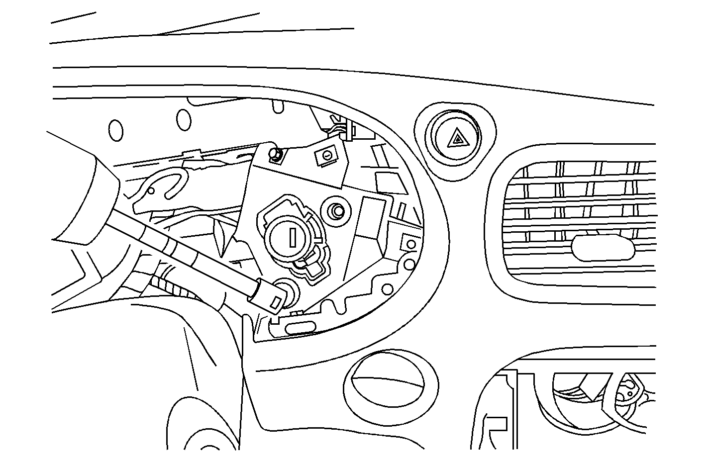
- Remove the ignition lock cylinder bezel.
- Set parking brake and shifter in the lowest gear position.
- Remove the shifter knob retainer and knob assembly.
- Remove the console trim plate.
- Remove the radio trim plate.
- Remove the radio.
- Remove the lock cylinder/ignition switch assembly to I/P retaining screws (3).
- Remove the two screws holding the collar to the switch assembly. Discard the collar.
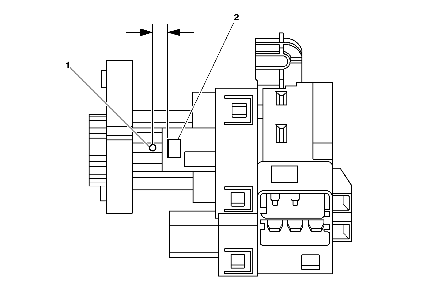
- Insert the customer's original key into the lock cylinder. Place key in the Run position. Locate the small cutout. See (2) inabove illustration. Insert a small screwdriver or suitable tool and depress the locking tab. Remove the lock cylinder housing assembly and discard.
- Install the new lock cylinder assembly to the housing.
- Install the new bracket from the kit to the ignition switch housing.
- Tape or cut off the 3-way (white, yellow and black wires) Passlock™ wiring harness connector to the vehicle's wiring harness as it will no longer be used.
- Locate the new wiring harness in the kit, P/N 22672039.
- Place a small piece of masking tape around each purple wire at the end which does not have a connector on it.
- On the masking tape you installed above, identify the purple wire from cavity D of the 10-way connector as circuit number 1807. The other purple wire from cavity F of the 10-way connector should be identified as circuit number 1500 (the instruction kit identifies this as 1580).
- Locate the new PASS-Key®III module, P/N 9353641, and the two-sided tape, P/N 15735177.
- Place one side of the 2-sided tape on the back side (side opposite the part number label) of the PASS-Key® module.
- Connect the wiring harness connector to the PASS-Key® module. Ensure it is positively locked in place.
- Wipe any dirt/dust from the left side of the steering column bracket and attach the PASS-Key® module to the steering column bracket with the two-sided tape. The wires should be hanging down.
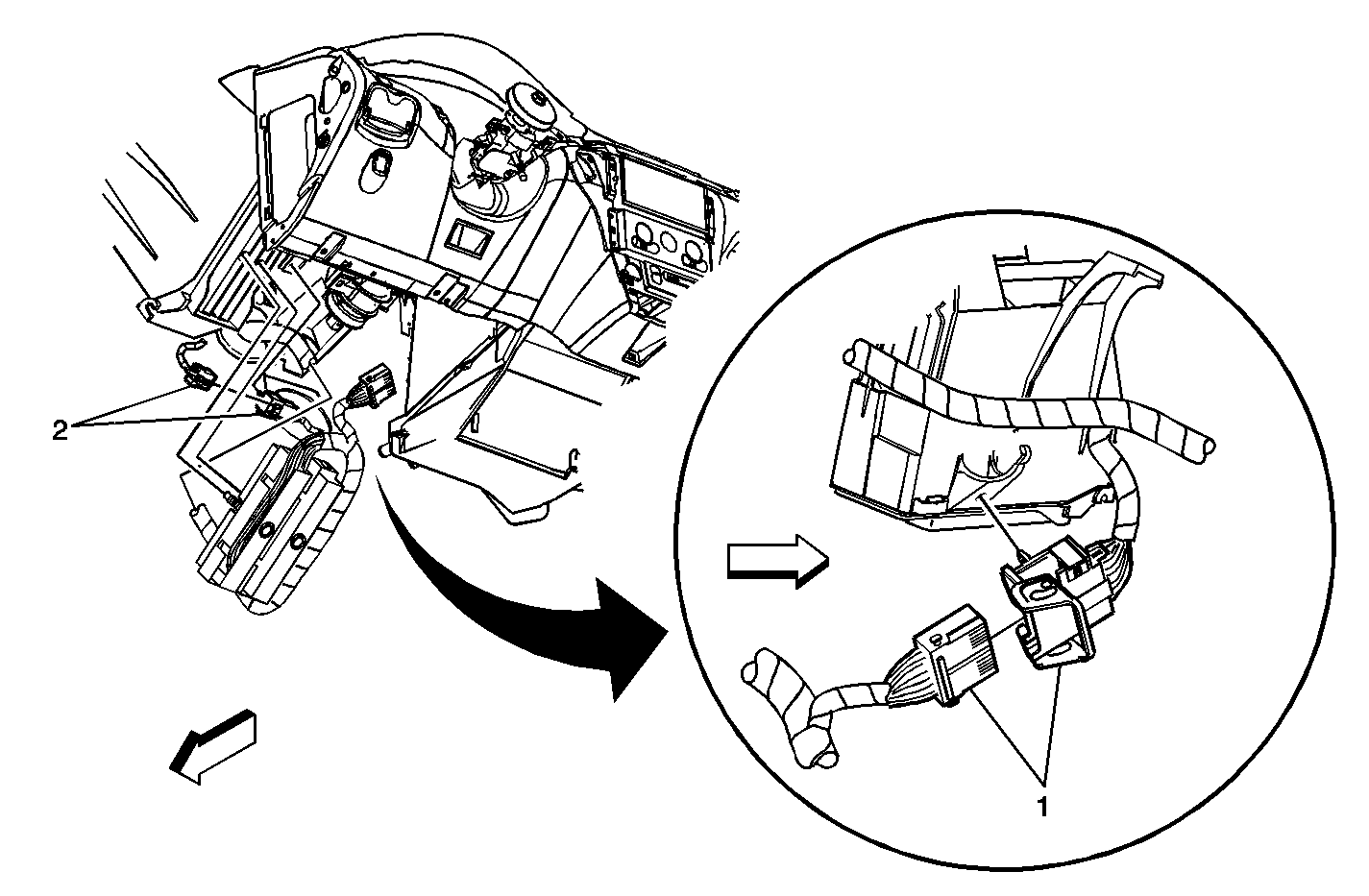
- Disconnect the ALDL connector from its mounting bracket.
- Route the 4 long wires without terminals to the area of the ALDL connector. Tape or tie the wires to other wiring harnesses to avoid rattles.
- The next step is to properly splice the four (4) wires from the retrofit kit into the vehicle's existing 3 wires at the ALDL connector and 1 wire at C200. See (1) in above illustration.
- The approved splicing procedure is listed here. You will need the J 38125-B Terminal Repair Kit for this procedure.
- Cut the service kit wires to proper length and splice them to the vehicle's wiring.
- Inspect the instrument panel cut-out for the ignition lock cylinder. If it is not a circle, it will have to be reshaped.
- Carefully reshape, if necessary, the ignition lock cylinder hole in the instrument panel to 48 mm (1-29/32 in) or until the grey portion of the key bezel will fit into the opening.
- Route the PASS-Key®III wiring harness connector to the ignition switch assembly and connect to the PASS-Key® sensor on the assembly. Ensure that the connector is fully seated.
- Place the ignition switch assembly behind the instrument panel and install the three (3) mounting fasteners.
- Install the instrument panel cluster to the instrument panel. Ensure the wiring harness is connected to the cluster.
- Install the instrument panel trim plate and install the 2 retainers.
- Install the radio. Ensure wiring and antenna leads are connected.
- Install the radio trim plate.
- Install the shifter trim plate to the console.
- Install the shifter knob and retainer clip.
- Place the shifter in the park position.
- Install the new ignition lock cylinder bezel light pipe assembly to the instrument panel.
- Reposition and attach the ALDL connector to the instrument panel mounting bracket.
- Reconnect the negative battery cable.
- Configure the BCM using the procedure below.
- Install the left and right side closeout panels.
- Be sure the Techline equipment has been updated with all the latest information. This includes the Techline terminal and the Tech 2.
- Connect the Tech 2 to the vehicle ALDL connector.
- Select SPS programming on the Tech 2.
- Request vehicle information.
- When the vehicle information request has been completed, take the Tech 2 to the Techline Terminal and perform the PCM SPS programming procedure.
- Reconnect the Tech 2 to the vehicle and reprogram the vehicle's Powertrain Control Module (PCM).
- Perform the "Vehicle Theft Deterrent Learn" procedure" for the PCM and PK3 module you have just installed using the Tech 2.
- Perform "Key Learn" for the other keys to be given to the customer.
- Check the PK3 system. Verify the vehicle engine will start and run with all new keys.
- Discard all previous customer keys and ensure customer does the same with all other keys for this vehicle in their possession.
To remove the lock cylinder from the lock cylinder housing, turn the housing so the silver collar of the lock cylinder is resting on the workbench. On the upper end of the housing, a slot can be seen. In this slot is the lock cylinder retainer, a tab. Using a small screw driver or other suitable tool, depress the tab while gently lifting the housing from the lock cylinder.
For ease in assembly, place the customer's original key in the lock cylinder and move it in slowly as you are placing the springs and tumblers in the key cylinder. This action will retain the assembled components as you are working.


Tighten
Tighten the bolts to 6 N·m(53 lb in).

| 49.1. | Open the harness. If the harness is taped, remove the tape. To avoid wiring insulation damage, use a sewing seam ripper in order to open the harness. If the harness has a black plastic conduit, pull out the desired wire. |
| 49.2. | Cut the wire to be spliced into. Ensure that each splice is at least 40 mm (1.5 in) away from other splices, harness branches and connectors. This helps prevent moisture from bridging adjacent splices and causing damage. |
| 49.3. | Strip approximately 7.5 mm (5/16 in) of insulation from each end of the wire to be spliced. |
| 49.4. | Select the proper clip to secure the splice. Follow the instructions in the J 38125-B in order to determine the proper clip size, crimp tool and anvil. |
| 49.5. | Overlap the stripped wire ends and hold them between your thumb and forefinger. |
| 49.6. | Center the splice clip over the stripped wires and hold the clip in place. Ensure that the wires extend beyond the clip in each direction and no insulation is caught under the clip. |
| 49.7. | Center the crimp tool over the splice clip and wires. |
| 49.8. | Apply steady pressure until the crimp tool closes. Ensure that no strands of wire are cut. |
| 49.9. | Apply 60/40 rosin core solder to the opening in the back of the clip. Follow the manufacturer's instructions for the solder equipment. |
| 49.10. | Tape the splice. Roll on enough tape in order to duplicate the thickness of the insulation on the existing wires. |
The black and white wire is to be spliced to the black and white wire from cavity 5 of the ALDL connector.
The orange wire is to be spliced to the orange wire from cavity 16 of the ALDL connector.
The purple wire you tagged as circuit 1807 is to be spliced to the purple wire in cavity 2 of the ALDL connector.
The purple wire you tagged as circuit 1500 is to be spliced to the purple wire in cavity B9 of C200
Tighten
Tighten the bolts to 6 N·m(53 lb in).
Tighten
Tighten the retainers to 3 N·m(25 lb in).
Tighten
Tighten the retainers to 3 N·m(25 lb in).
Tighten
Tighten the radio mounting screws to 3 N·m (25 lb in).
For 1999 model year vehicles:
| - | Use the Tech 2 and SPS programming. |
| - | Use the Techline Terminal and select TIS 2000, SPS, Programming, Enter VIN, BFC. |
| - | When the calibration screen is displayed, select "New BFC configuration file for vehicles retrofitted to eliminate RFA communication interference" #22604560. |
| - | Select the proper calibration based on the engine in the vehicle (22604560 for the 4-cylinder and 22604561 for the V6 engine). |
| - | Download to the Tech 2. |
| - | With the Tech 2 connected to the vehicle, perform the BCM programing procedure. |
For 2000 model year vehicles:
| - | Use the Tech 2: Body diagnostics, |
| - | and the new BCM setup screens. |
Parts Information
Part Number | Description | Qty |
|---|---|---|
22672037 | PASS-Key®III update kit for 1999 Chevrolet Alero | 1 |
22672038 | PASS-Key®III update kit for 2000 Chevrolet Alero | 1 |
Parts are currently available from GMSPO.
Warranty Information
For vehicles repaired under warranty, use:
Labor Operation | Description | Labor Time |
|---|---|---|
R4802 | Update Vehicle to PASS-Key®III | 2.3 hrs |
