Restraint Devices

The Supplemental Inflatable Restraint (SIR) system helps supplement the protection offered by the driver's seat belt. The SIR system deploys an air bag from the center of the steering wheel during certain frontal crashes.
The knee bolster helps absorb crash energy. The knee bolster is located beneath the instrument panel in the driver's area. The steering column is collapsible. The steering column also absorbs crash energy.

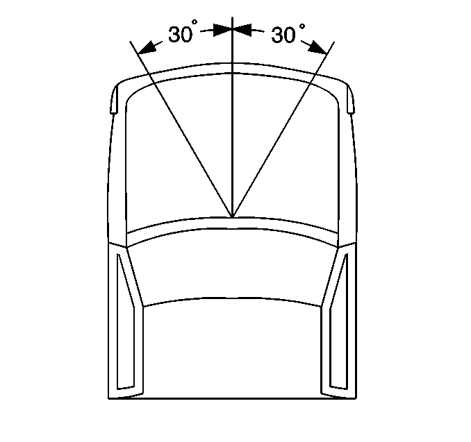
The air bag deploys when the vehicle is involved in a frontal crash of sufficient force, up to 30° off the centerline of the vehicle.
System Description
The SIR system consists primarily of the deployment loop and the inflatable restraint Diagnostic Energy Reserve Module (DERM). The deployment loop mainly supplies current through the inflator module in the steering wheel. This causes deployment of the air bag during certain frontal crashes.
The deployment loop consists of the following components:
| • | The inflatable restraint arming sensor |
| • | The inflatable restraint steering wheel module coil |
| • | The inflatable restraint steering wheel inflator module |
| • | Inflatable restraint discriminating sensors |
The inflatable restraint arming sensor transfers power to the inflator module. The inflator module is on the high side (power side) of the deployment loop. Either of the discriminating sensors can supply ground to the inflatable restraint steering wheel inflator module. The inflatable restraint discriminating sensors are on the low side (ground side) of the deployment loop. In order to supply enough current to deploy the inflator module, the inflatable restraint arming sensor and at least one of the inflatable restraint discriminating sensors must close simultaneously.
The DERM supplies the deployment loop with a 36 Volt Loop Reserve (36 VLR) in order to ensure deployment of the air bag if the ignition feed to the arming sensor is lost during a frontal crash.
The DERM monitors the deployment loop together with the resistors in the inflatable restraint arming sensor and the resistors in the inflatable restraint discriminating sensors. These resistors enable the DERM to detect circuit and component malfunctions within the deployment loop. The DERM monitors each component during normal conditions. If the monitored voltage falls outside of the expected limits, the following will occur.
- The DERM will indicate a malfunction through the storage of a diagnostic trouble code.
- The AIR BAG warning lamp will light up.
