| Table 1: | Frequency Vs. RPM |

Circuit Description
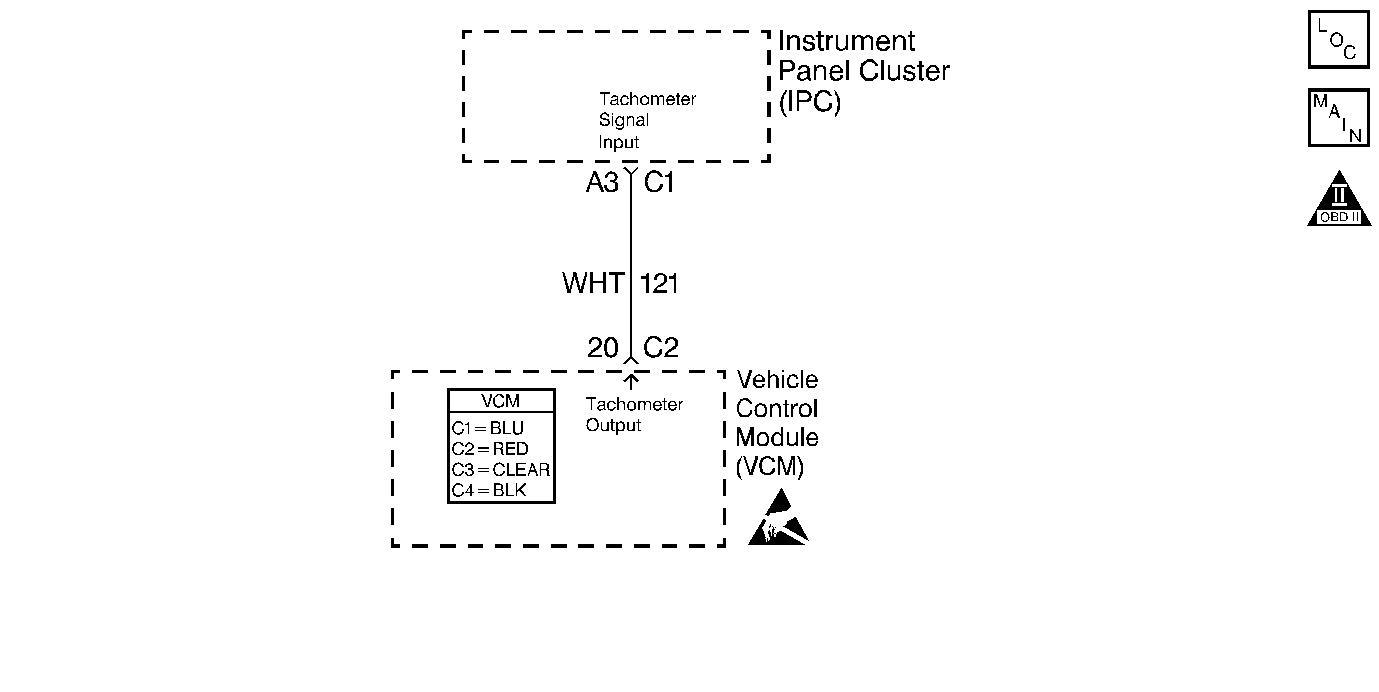
The IPC supplies 12 volts to the tachometer circuit. The VCM Pulse Width Modulates (PWM) the tachometer circuit. The PWM signal will vary with the speed of the engine.
Diagnostic Aids
Use the following table in order to verify correct VCM operation of the TACH circuit.
Commanded Output (RPM) | 500 | 1000 | 1500 | 2000 | 2500 | 3000 | 3500 | 4000 | 4500 | 5000 | 5500 | 6000 |
|---|---|---|---|---|---|---|---|---|---|---|---|---|
VCM PWM Signal (Hz) | 16.4 | 32.9 | 49.4 | 66.7 | 83.1 | 99.7 | 116.1 | 133.6 | 150.1 | 166.6 | 183.1 | 200.4 |
Test Description
The number(s) below refer to the step number(s) on the diagnostic table.
-
This step checks the IPC's ability to control the tachometer needle.
-
This step checks for proper tachometer operation.
-
This step checks the VCM's ability to send an accurate PWM signal to the IPC.
If the Tachometer Output matches the Frequency Vs. RPM table the fault must be a poor connection at the IPC or an internal IPC failure.
Step | Action | Value(s) | Yes | No |
|---|---|---|---|---|
1 |
Important: Before clearing the DTCs, record Freeze Frame and the Failure Records for reference with a scan tool. This data will be lost when the Clear DTC Information function is used. Did you perform the Powertrain On-Board Diagnostic (OBD) System Check? | -- | ||
Does the tachometer needle sweep when commanded? | -- | Go to Instrument Cluster System Check in Instrument Panel, Gauges and Console | ||
Does the tachometer value displayed by the IPC match the commanded TACH output? | 600 RPM 6000 RPM | System OK | ||
Does the frequency output of the TACH circuit match the Frequency Vs. RPM table? | 600 RPM 6000 RPM | Go to Instrument Cluster System Check in Instrument Panel, Gauges and Console | ||
5 | Check the Tachometer Output circuit for an open, short to ground or a short to voltage. Did you find a problem? | -- | ||
6 | Repair the circuit as necessary. Refer to Wiring Repairs in Wiring Systems. Is the action complete? | -- | -- | |
7 | Check for a poor connection at the VCM. Repair as necessary. Refer to Wiring Repairs in Wiring Systems. Did you find a problem? | |||
8 |
Is the action complete? | -- | -- |
