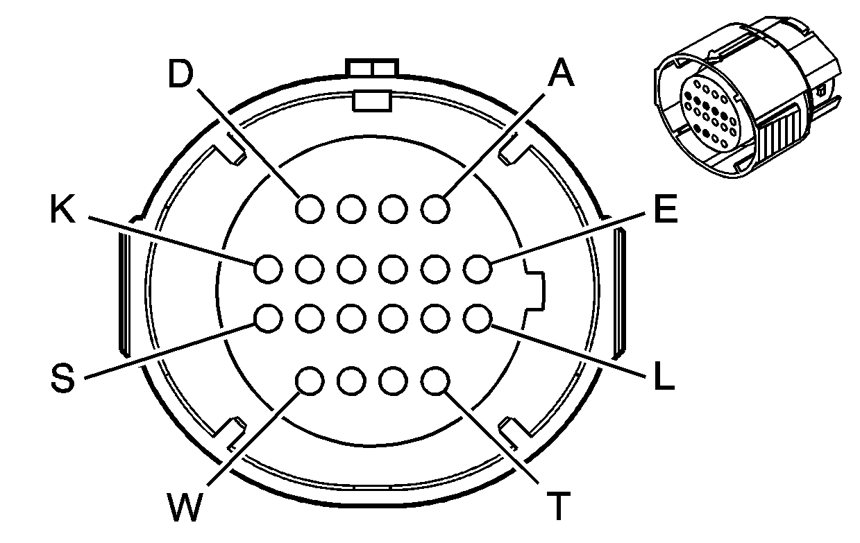
| Table 1: | Inline Harness Connector, Engine Side |
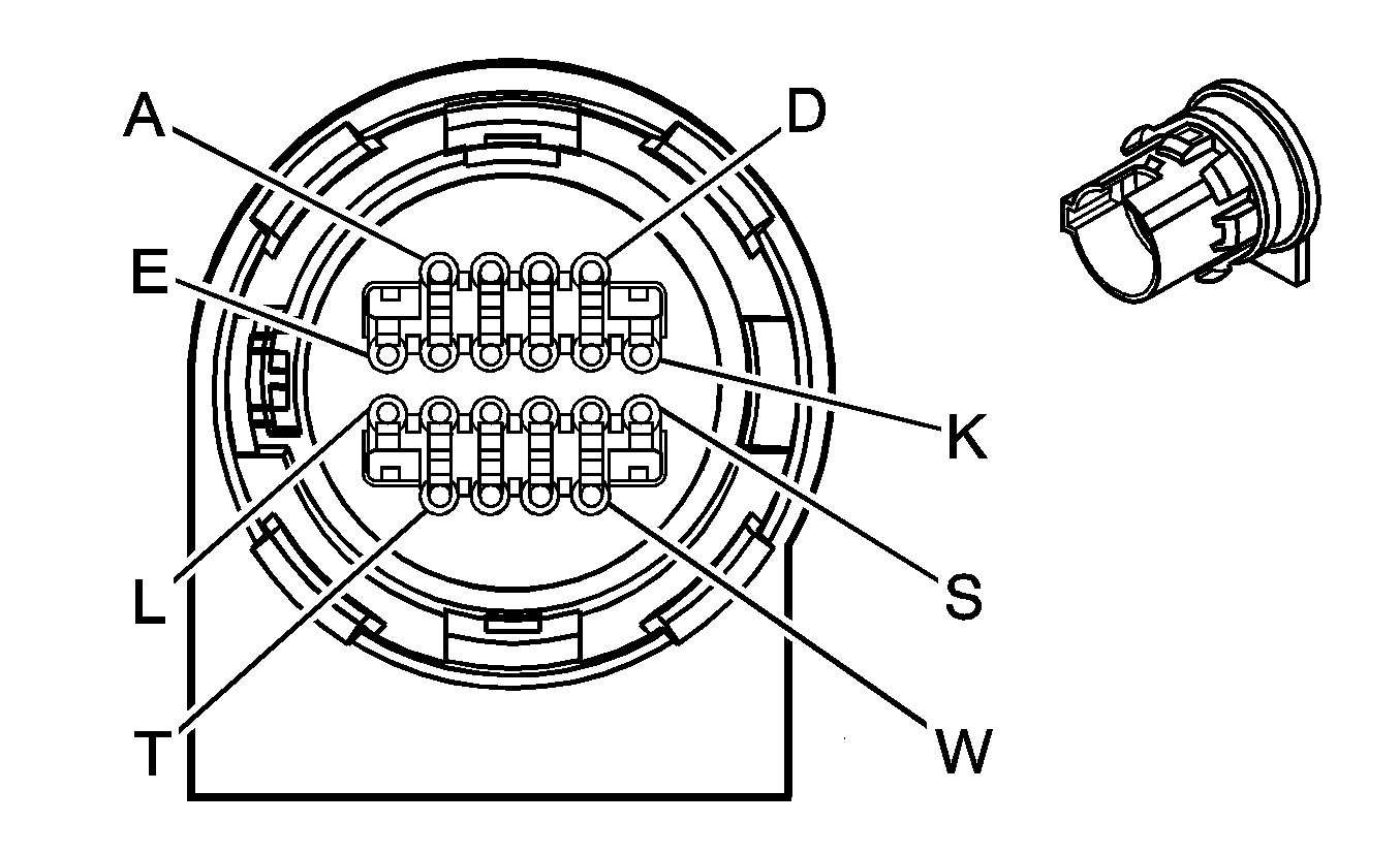
| Table 2: | Inline Harness Connector, Transmission Side |

| |||||||
|---|---|---|---|---|---|---|---|
Connector Part Information |
| ||||||
Pin | Wire Color | Circuit No. | Function | ||||
A | LT GRN | 1222 | 1-2 Shift Solenoid Valve Control | ||||
B | YEL/BLK | 1223 | 2-3 Shift Solenoid Valve Control | ||||
C | RED/BLK | 1228 | Pressure Control (PC) Solenoid Valve High Control | ||||
D | LT BLU/WHT | 1229 | PC Solenoid Valve Low Control | ||||
E | PNK | 1020 | OFF/RUN/CRANK Voltage | ||||
F-K | -- | -- | Not Used | ||||
L | YEL/BLK | 1227 | Transmission Fluid Temperature (TFT) Sensor Signal | ||||
M | BLK | 470 | Low Reference | ||||
N | PNK | 1224 | TFP Switch Signal A | ||||
P | RED | 1226 | TFP Switch Signal C | ||||
R | DK BLU | 1225 | TFP Switch Signal B | ||||
S | WHT | 687 | 3-2 Shift Solenoid Valve Control | ||||
T | TAN/BLK | 422 | Torque Converter Clutch Solenoid Valve Control | ||||
U | BRN | 418 | Torque Converter Clutch Pulse Width Modulation Solenoid Valve Control | ||||
V-W | -- | -- | Not Used | ||||

| |||||||
|---|---|---|---|---|---|---|---|
Connector Part Information |
| ||||||
Pin | Wire Color | Circuit No. | Function | ||||
A | LT GRN | 1222 | 1-2 Shift Solenoid Valve Control | ||||
B | YEL | 1223 | 2-3 Shift Solenoid Valve Control | ||||
C | PPL | 1228 | Pressure Control (PC) Solenoid Valve High Control | ||||
D | LT BLU | 1229 | PC Solenoid Valve Low Control | ||||
E | RED | 839 | Ignition 1 Voltage | ||||
L | BRN | 1227 | Transmission Fluid Temperature (TFT) Sensor Signal | ||||
M | GRY | 452 | Low Reference | ||||
N | PNK | 1224 | TFP Switch Signal A | ||||
P | ORN | 1226 | TFP Switch Signal C | ||||
R | DK BLU | 1225 | TFP Switch Signal B | ||||
S | WHT | 687 | 3-2 Shift Solenoid Valve Control | ||||
T | BLK | 422 | Torque Converter Clutch Solenoid Valve Control | ||||
U | TAN | 418 | Torque Converter Clutch Pulse Width Modulation Solenoid Valve Control | ||||
V-W | -- | -- | Not Used | ||||
