GM Service Manual Online
For 1990-2009 cars only
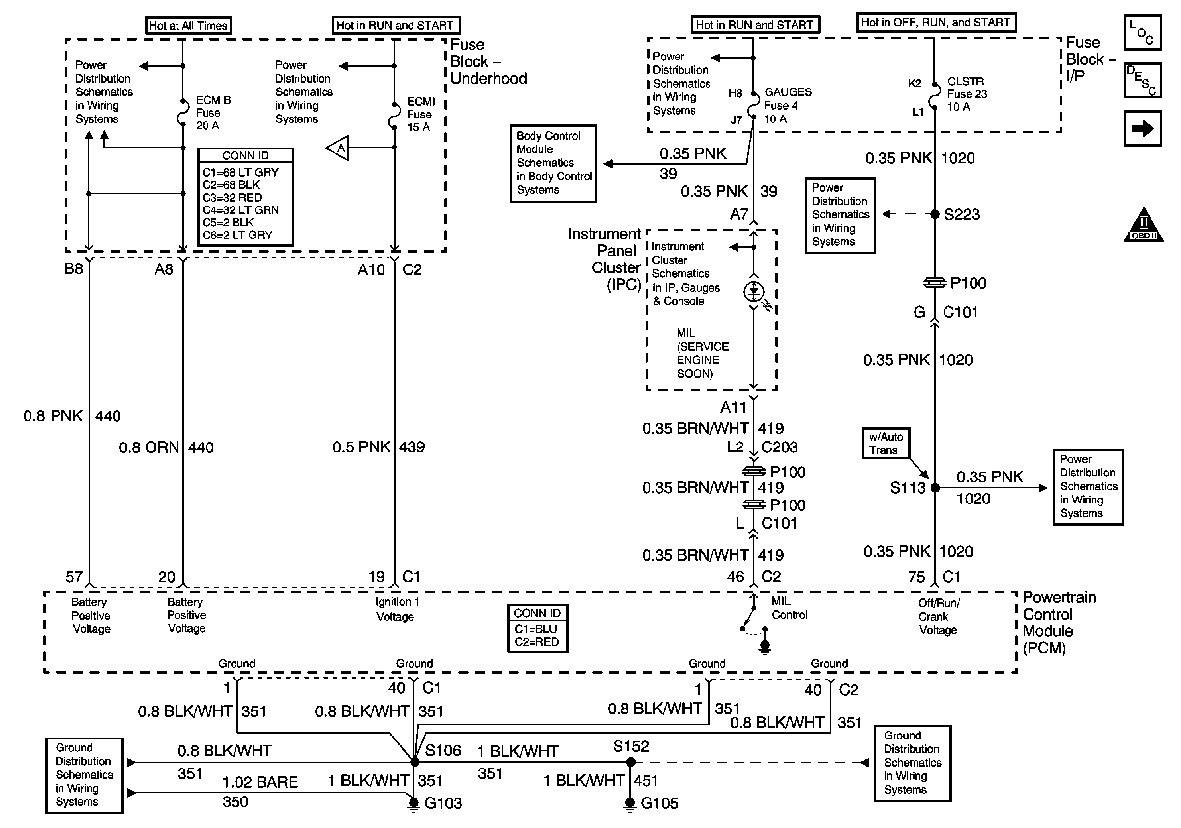
Figure 1:

Power, Ground, MIL and VCM


Object Number: 680474  Size: FS
Master Electrical Component List
Powertrain Control Module Description
Data Link Connector (DLC)
OBD II Symbol Description Notice
A/C, ABS, ECM B, FOG LP, STOP LP, VECHMSL, and TRCHMSL Fuses
ECM I Fuse
Fuel Injection Controls
Power and Ground
Ign START, RUN and ACC Bus Bar
Power
CLSTR Fuse
CLSTR Fuse
G103 and G105
G103 and G105
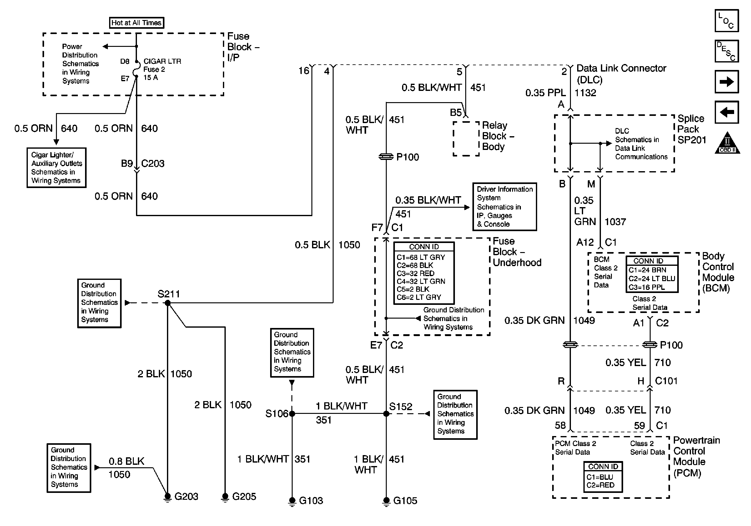
Figure 2:

Data Link Connector (DLC)


Object Number: 680479  Size: FS
Master Electrical Component List
Powertrain Control Module Description
Ignition Controls
Power, Ground, MIL and VCM
OBD II Symbol Description Notice
STUD 2, INT BAT, CIGAR LTR, CTSY LP and PWR LKS Fuses
Cigar Lighter/Auxiliary Outlets Schematics
G203 and G205
G203 and G205
G103 and G105
Driver Information Schematics
Splice Pack SP201 and Modules
G103 and G105
G103 and G105
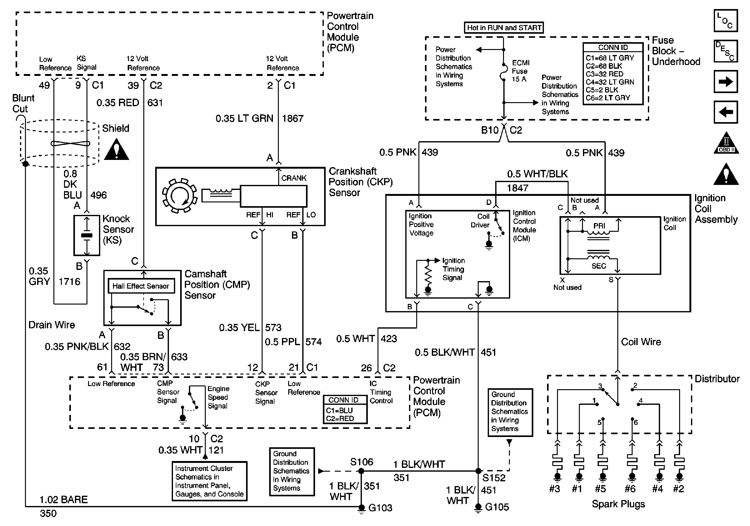
Figure 3:

Ignition Controls


Object Number: 680484  Size: FS
Master Electrical Component List
Distributor Ignition (DI) System Description
Fuel Level Sensor
Data Link Connector (DLC)
OBD II Symbol Description Notice
Engine Controls Schematic Icons
Ign START, RUN and ACC Bus Bar
ECM I Fuse
Data Link Connector (DLC), VCM and Engine Oil Pressure Gauge Sensor
G103 and G105
G103 and G105
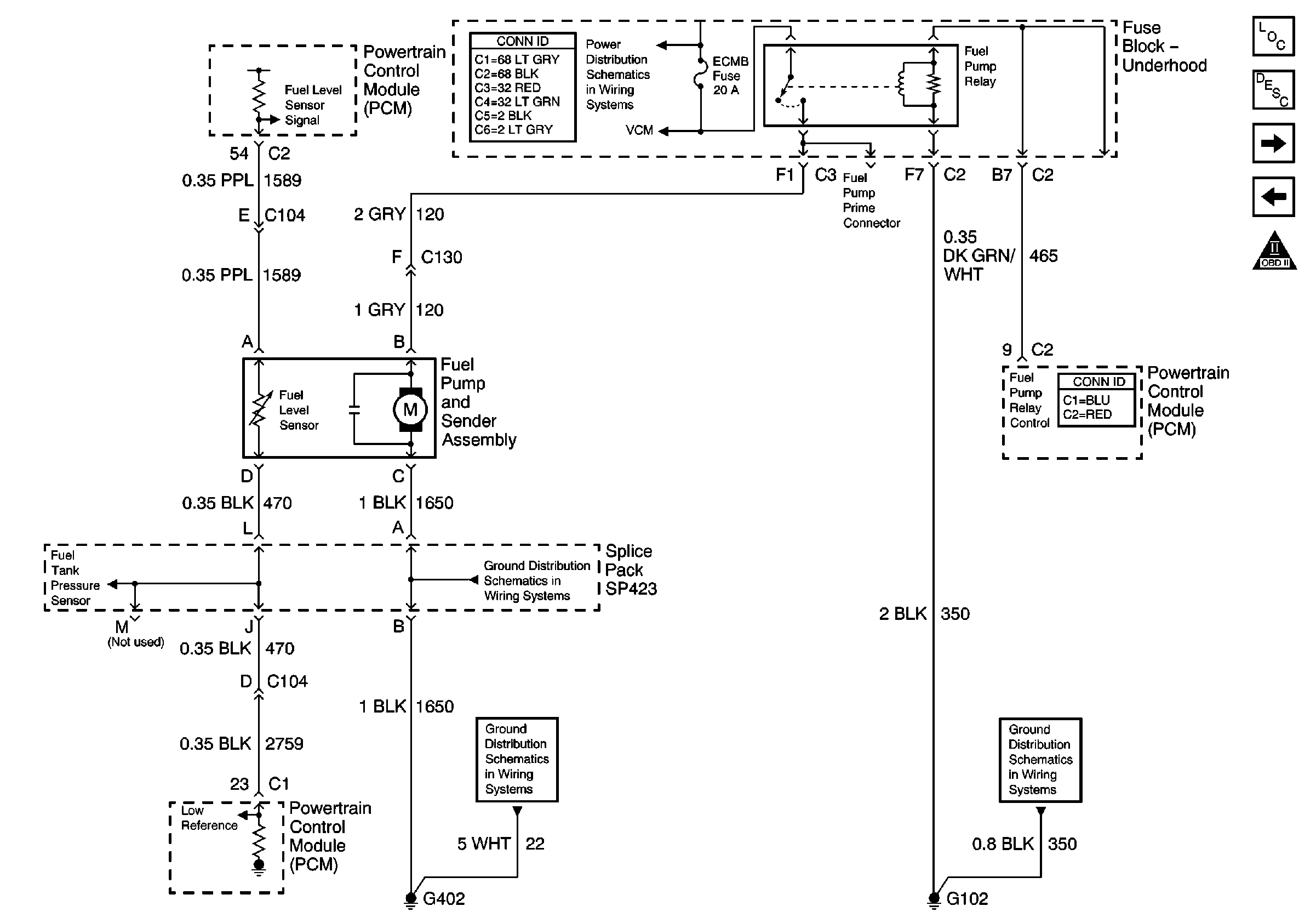
Figure 4:

Fuel Level Sensor


Object Number: 680488  Size: FS
Master Electrical Component List
Fuel System Description
Fuel Injection Controls
Ignition Controls
OBD II Symbol Description Notice
A/C, ABS, ECM B, FOG LP, STOP LP, VECHMSL, and TRCHMSL Fuses
Engine Sensors
G402 and G420
G402 and G420
G102
Figure 5:

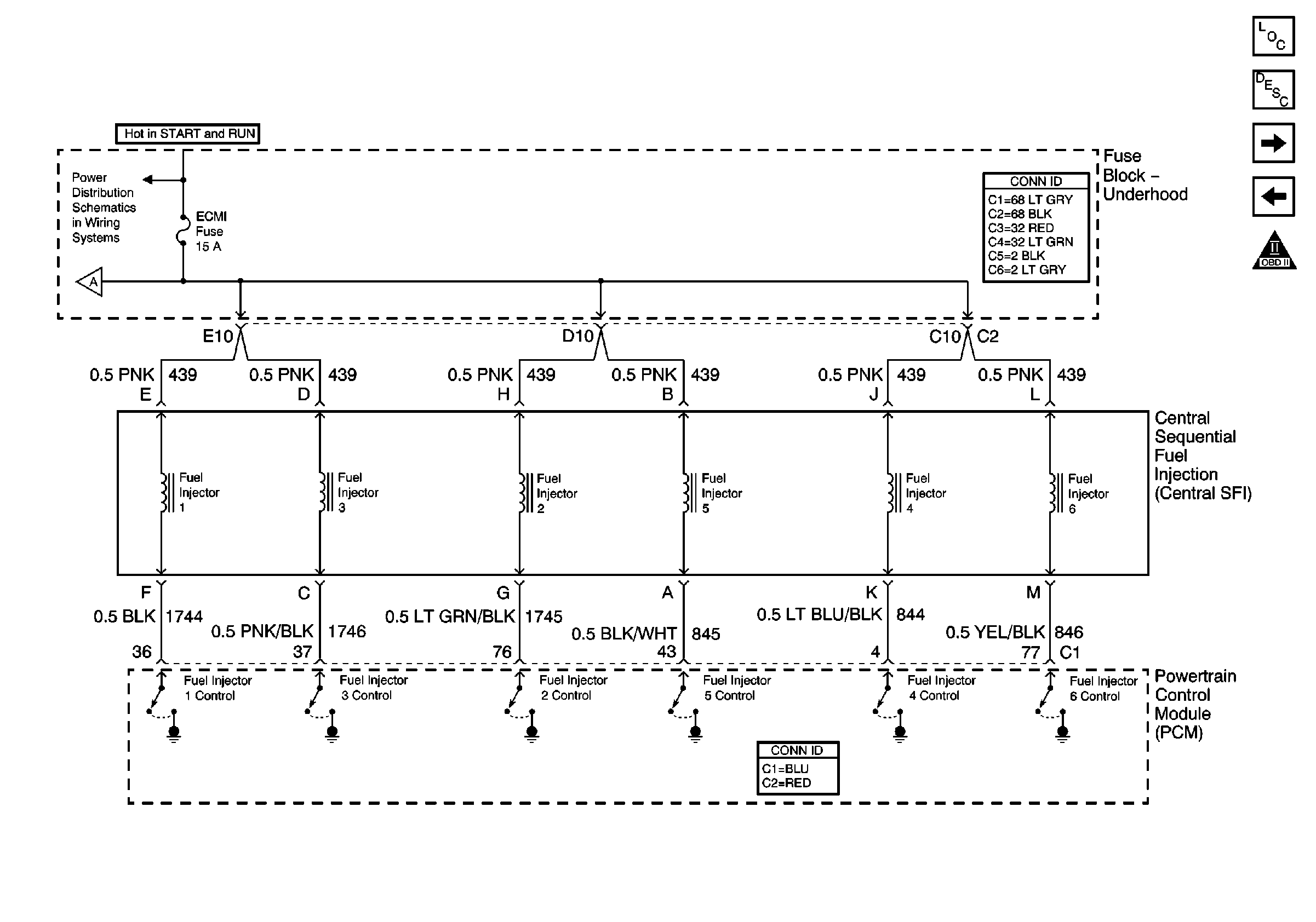
Fuel Injection Controls


Object Number: 680493  Size: FS
Master Electrical Component List
Fuel System Description
Engine Sensors
Fuel Level Sensor
OBD II Symbol Description Notice
ECM I Fuse
Power, Ground, MIL and VCM
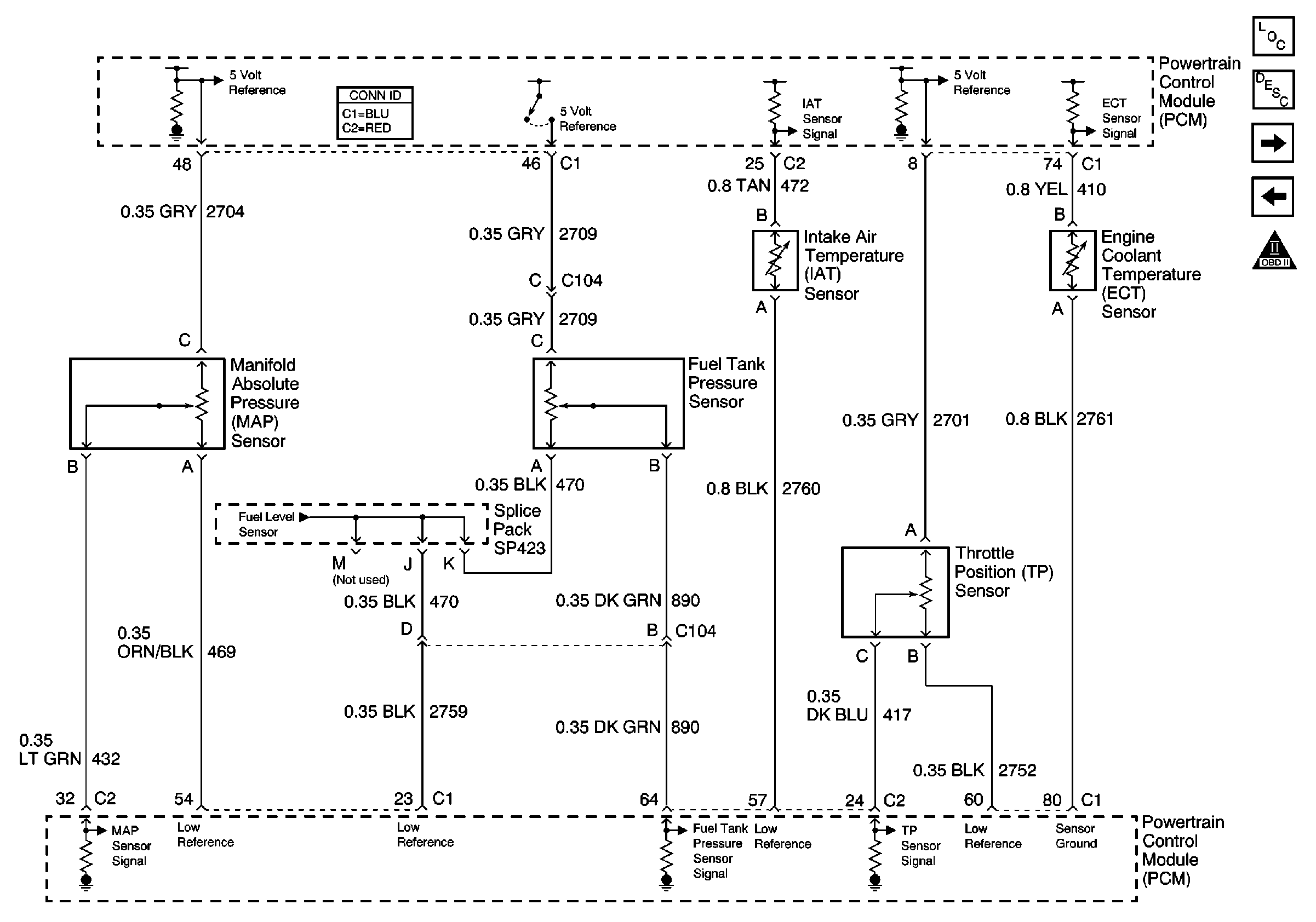
Figure 6:

Engine Sensors


Object Number: 680496  Size: FS
Master Electrical Component List
Powertrain Control Module Description
Heated Oxygen Sensors
Fuel Injection Controls
OBD II Symbol Description Notice
Fuel Level Sensor
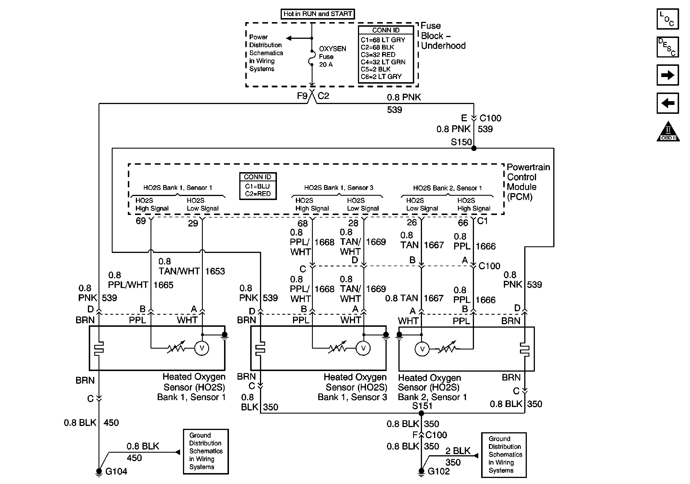
Figure 7:

Heated Oxygen Sensors


Object Number: 680499  Size: FS
Master Electrical Component List
Powertrain Control Module Description
MAF and IAC Controls
Engine Sensors
OBD II Symbol Description Notice
Ign START, RUN and ACC Bus Bar
G104, G106, G107, G108 and G118
G102
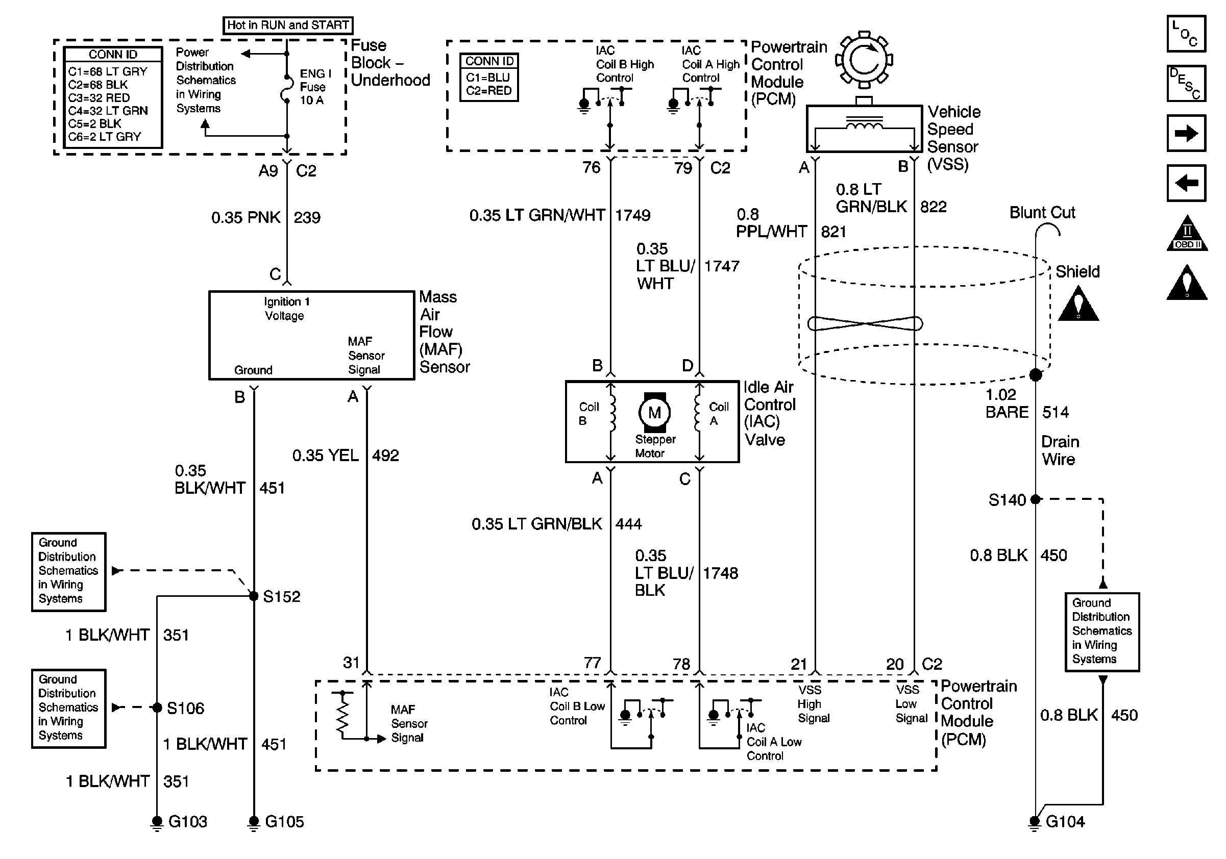
Figure 8:

MAF and IAC Controls


Object Number: 680504  Size: FS
Master Electrical Component List
Powertrain Control Module Description
Vehicle Speed Outputs and Overhead Console Link
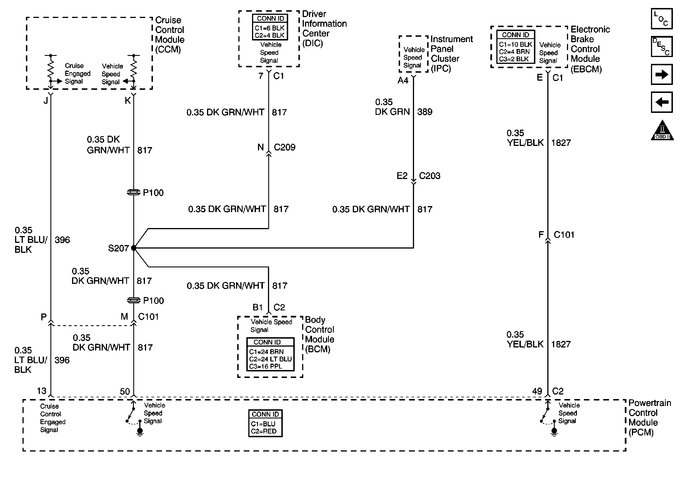
Heated Oxygen Sensors
OBD II Symbol Description Notice
Engine Controls Schematic Icons
B/U LP, OXYSEN, ENG I, TRL B/U, VEH B/U and BTSI Fuses
G103 and G105
G103 and G105
Engine Controls Schematic Icons
G104, G106, G107, G108 and G118
Figure 9:

Vehicle Speed Outputs and Overhead Console Link


Object Number: 680507  Size: FS
Master Electrical Component List
Powertrain Control Module Description
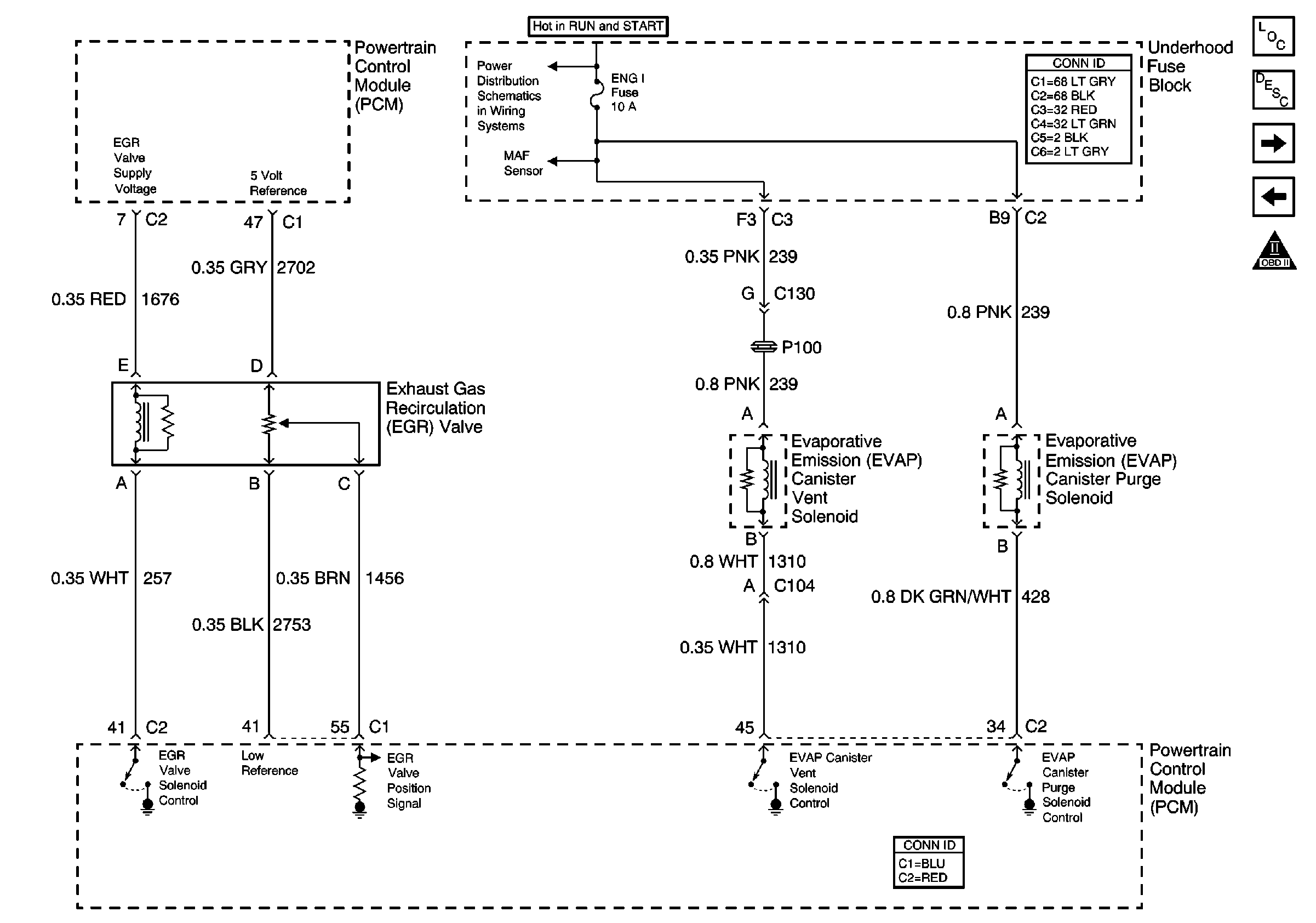
EGR Valve and EVAP Valves
MAF and IAC Controls
OBD II Symbol Description Notice
Figure 10:

EGR Valve and EVAP Valves


Object Number: 680508  Size: FS
Master Electrical Component List
Powertrain Control Module Description
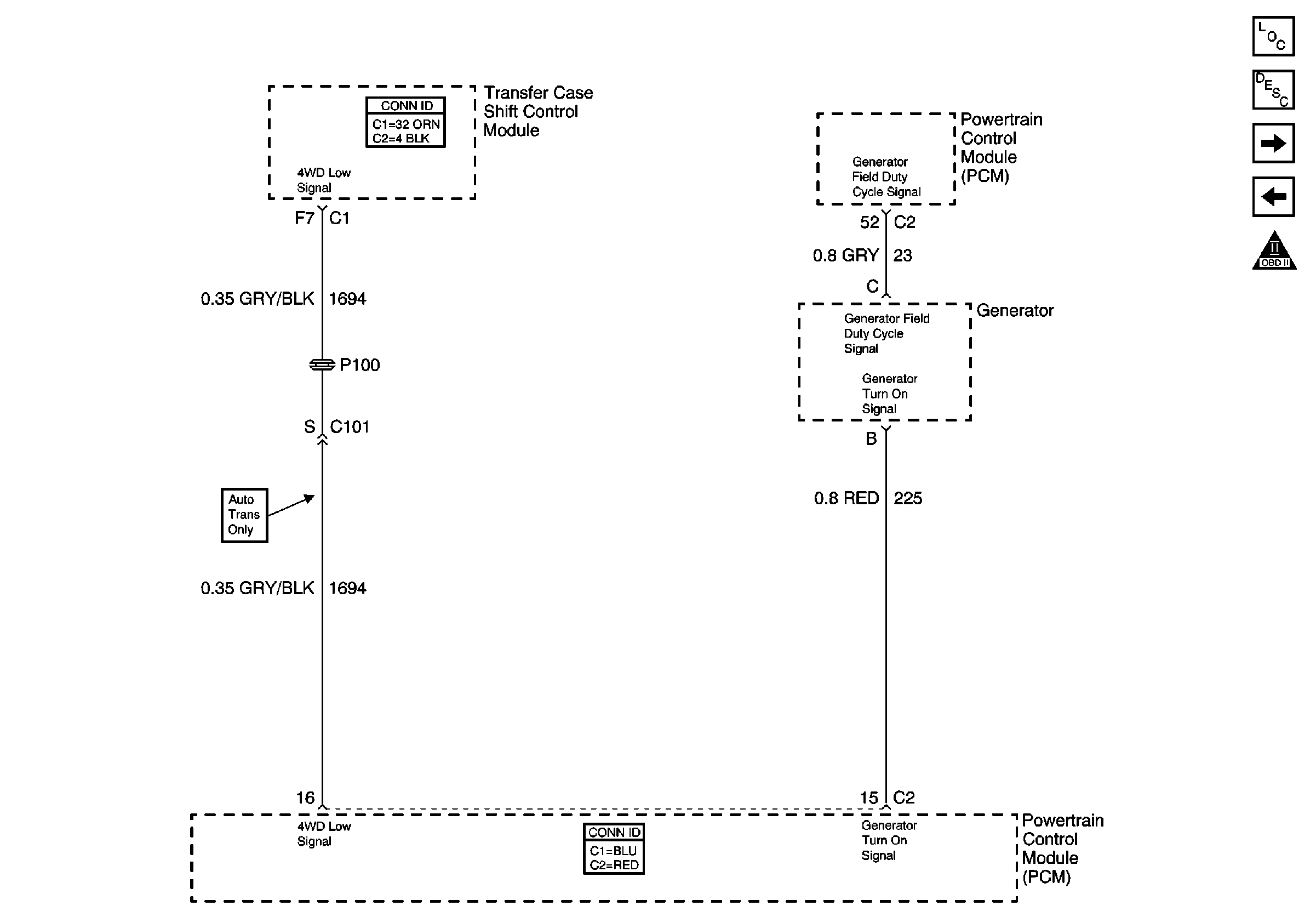
4WD Indicator Signal, and Generator
Vehicle Speed Outputs and Overhead Console Link
OBD II Symbol Description Notice
B/U LP, OXYSEN, ENG I, TRL B/U, VEH B/U and BTSI Fuses
MAF and IAC Controls
Figure 11:

4WD Indicator Signal, and Generator


Object Number: 680510  Size: FS
Master Electrical Component List
Powertrain Control Module Description
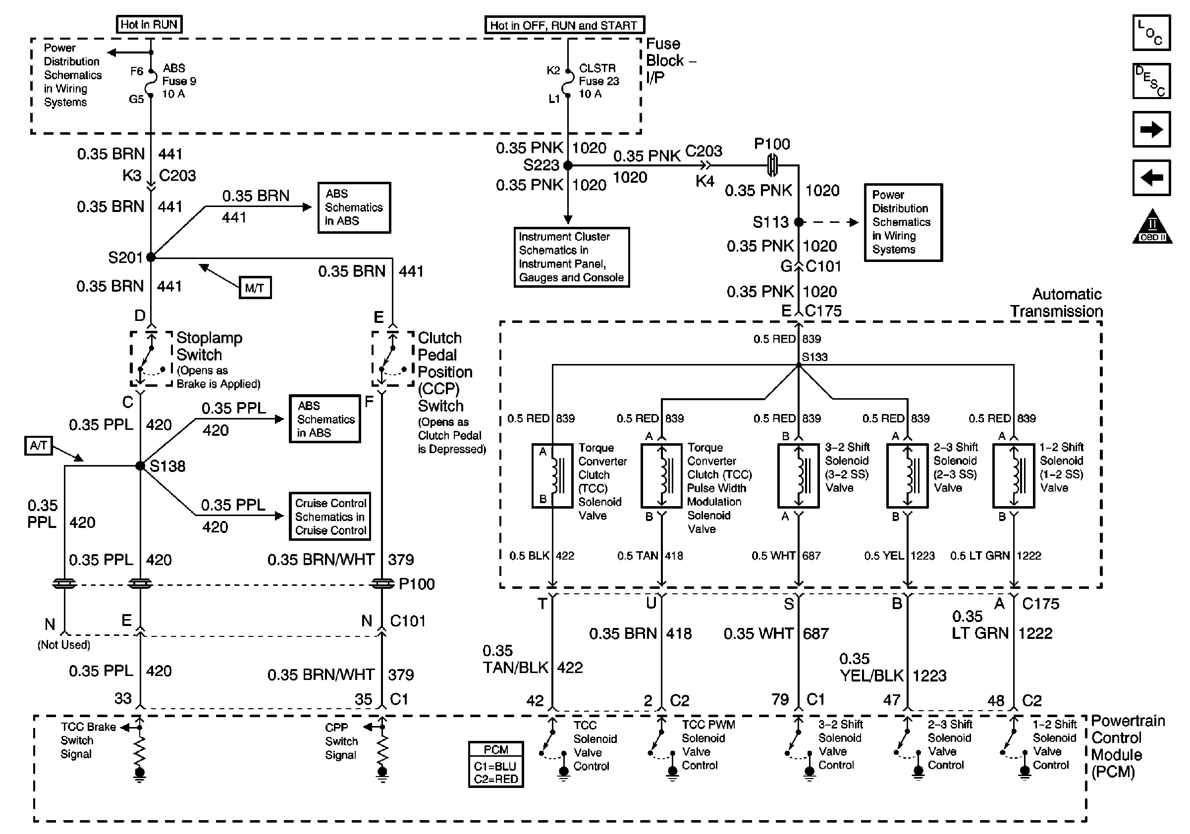
Automatic Transmission Valve Controls
EGR Valve and EVAP Valves
OBD II Symbol Description Notice
Figure 12:

Automatic Transmission Valve Controls


Object Number: 680511  Size: FS
Master Electrical Component List
Powertrain Control Module Description
Automatic Transmission and PNP Switch Inputs
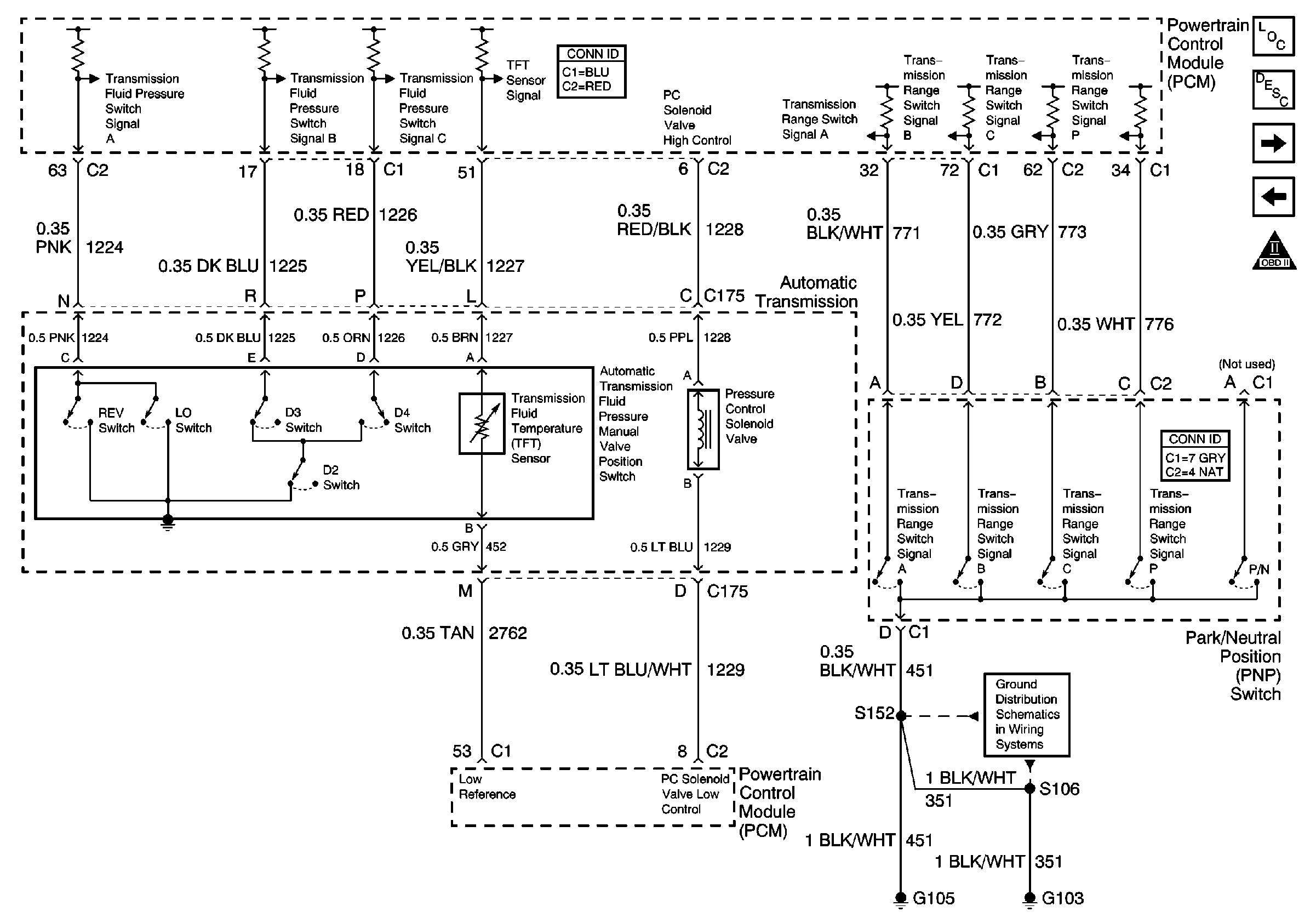
4WD Indicator Signal, and Generator
OBD II Symbol Description Notice
Ign RUN and START Bus Bar
EBCM Power and Ground
Cruise Control Schematics
Power
CLSTR Fuse
Figure 13:

Automatic Transmission and PNP Switch Inputs


Object Number: 680512  Size: FS
Master Electrical Component List
Powertrain Control Module Description
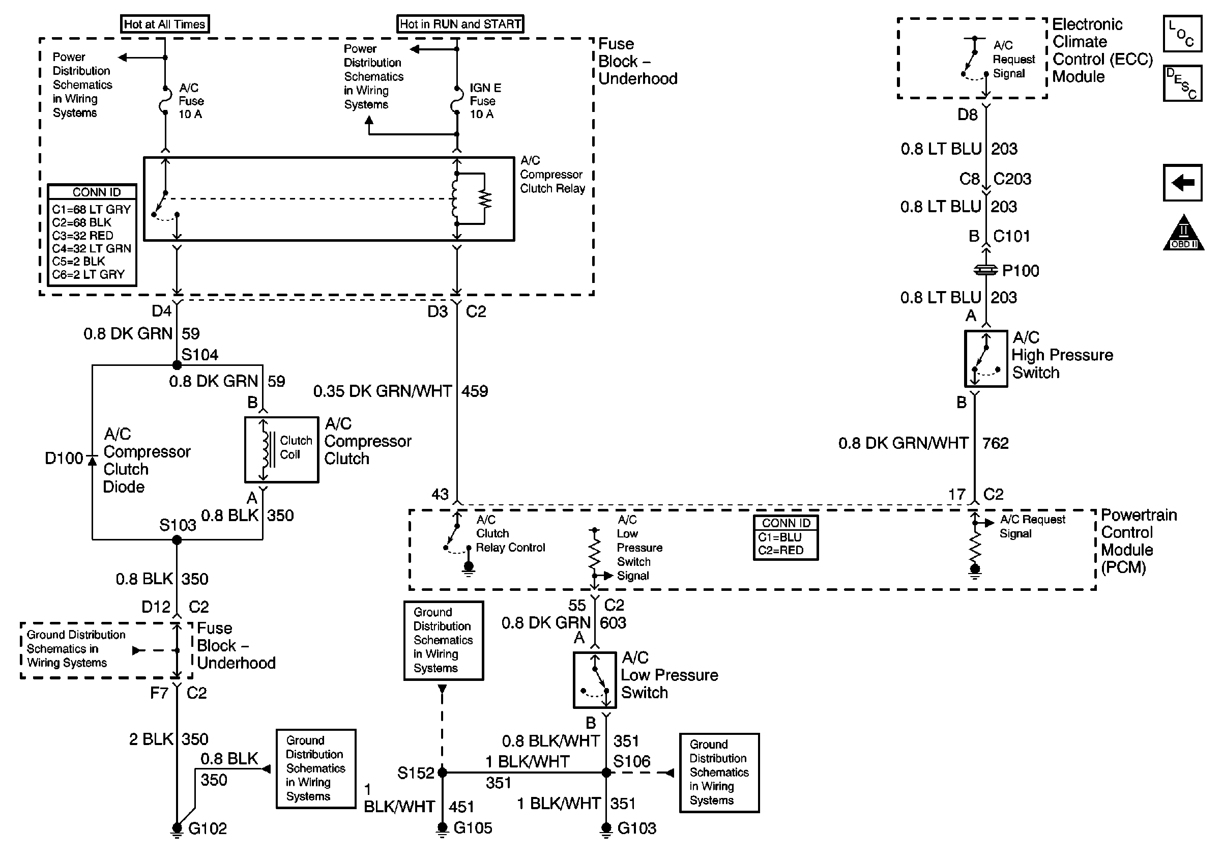
A/C Compressor Controls
Automatic Transmission Valve Controls
OBD II Symbol Description Notice
G103 and G105
Figure 14:

A/C Compressor Controls


Object Number: 680513  Size: FS
Master Electrical Component List
Powertrain Control Module Description
Automatic Transmission and PNP Switch Inputs
OBD II Symbol Description Notice
B+ Bus Bar
IGN E, GAUGES, and SIR Fuses
G102
G102
G103 and G105
G103 and G105