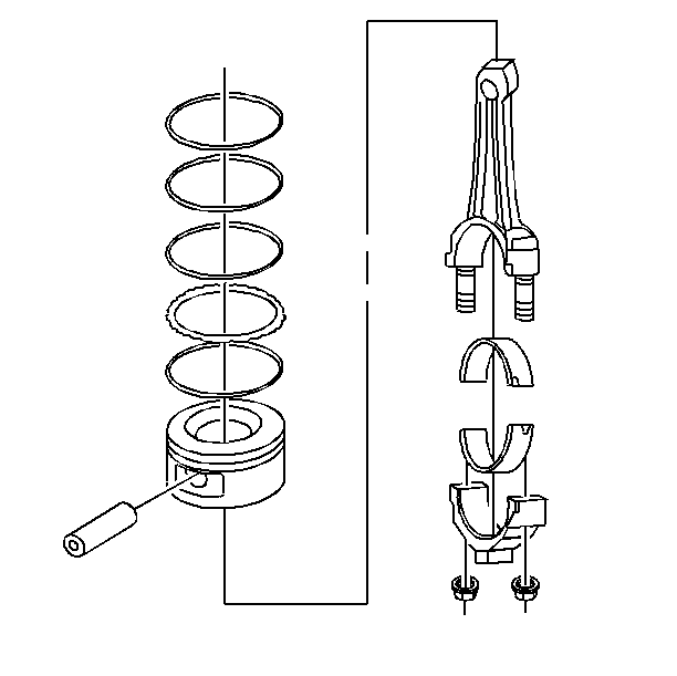
Important: Measurement of all components should be taken with the components at room temperature.
Do not use a wire brush in order to clean any part of the piston.
- Clean the piston and connecting rod in solvent.
Caution: Wear safety glasses in order to avoid eye damage.
- Dry the components with compressed air.
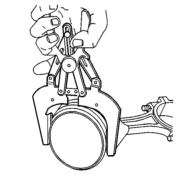
- Clean the piston ring grooves with a suitable ring groove cleaning tool.
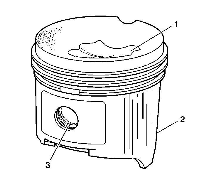
- Clean the piston oil lubrication holes and slots.
- Inspect the piston for the following:
| • | Eroded areas (1) on the top of the piston |
| • | Scuffed or damaged skirt (2) |
| • | Damage to the pin bore (3) |
| • | Cracks in the piston ring lands, the piston skirt, or the pin bosses |
| • | Piston ring grooves for nicks, burrs, or other warpage which may cause the piston ring to bind |
- Inspect the piston pin for scoring, wear or other damage.
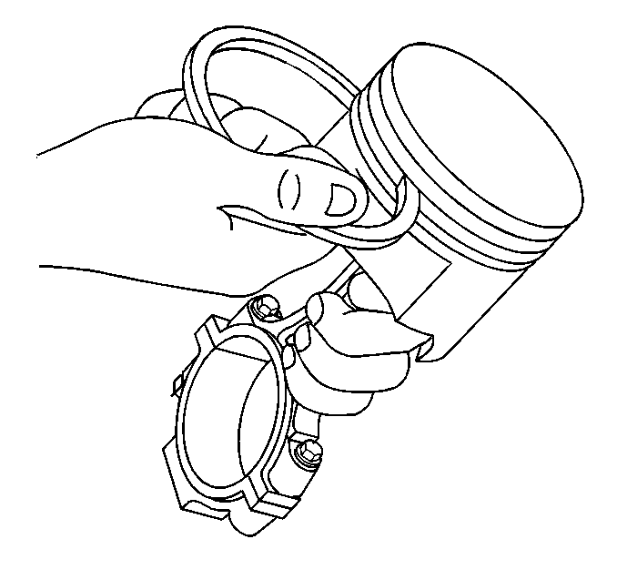
- Measure the piston ring-to-piston ring groove side clearance.
| 7.1. | Insert the edge of the piston ring into the piston ring groove. |
| 7.2. | Roll the piston ring completely around the piston. |
| • | If binding is caused by a distorted piston ring groove, MINOR imperfections may be removed with a fine file. |
| • | If binding is caused by a distorted piston ring, replace the piston ring. |
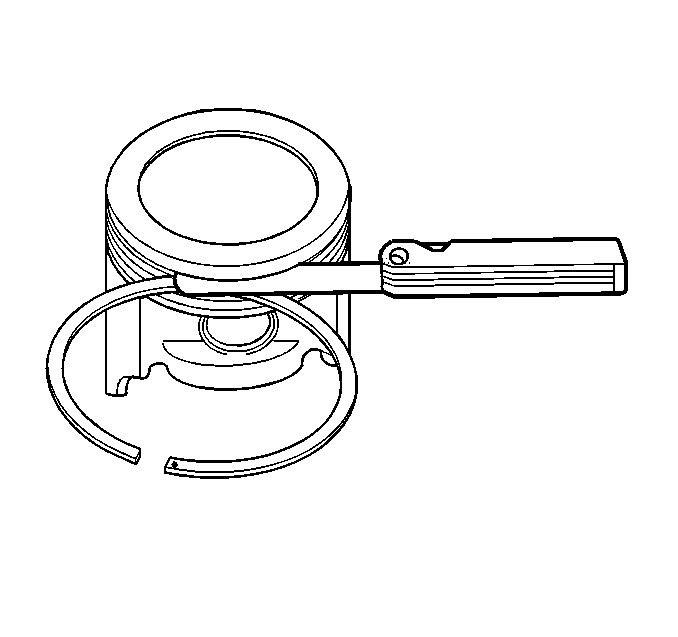
- Measure the piston ring side clearance with a feeler gauge.
- If the side clearance is too small, try another piston ring set.
- If the proper piston ring-to-piston ring groove clearance cannot be achieved, replace the piston and pin assembly.
- To determine the proper piston ring side clearance, refer to
Engine Mechanical Specifications
.
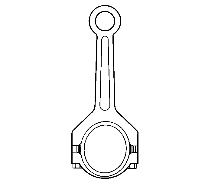
- Inspect the connecting rod for an out-of-round bearing bore. Refer to
Engine Mechanical Specifications
.
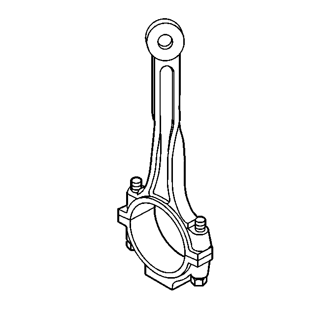
- Inspect the connecting rod for twisting.
- Inspect the connecting rod for damage to the bearing cap and bolt threads.
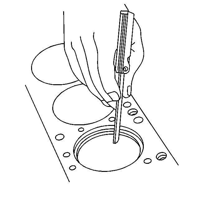
- Measure the piston compression ring end gap.
| | Important: Fit each compression ring to the cylinder in which it will be used.
|
| 15.1. | Place the compression ring into the cylinder bore. |
| 15.2. | Push the compression ring into the cylinder bore to approximately 6.5 mm (0.25 in) above the ring travel. |
The ring must be square to the cylinder wall.
| 15.3. | Use a feeler gage in order to measure the end gap. |

Important: Measurement of all components should be taken with the components at
room temperature.
Do not use a wire brush in order to clean any part of the piston.
- Clean the piston and connecting rod in solvent.
Caution: Wear safety glasses in order to avoid eye damage.
- Dry the components with compressed air.

- Clean the piston ring grooves with a suitable
ring groove cleaning tool.

- Clean the piston oil lubrication holes
and slots.
- Inspect the piston for the following:
| • | Eroded areas (1) on the top of the piston |
| • | Scuffed or damaged skirt (2) |
| • | Damage to the pin bore (3) |
| • | Cracks in the piston ring lands, the piston skirt, or the pin
bosses |
| • | Piston ring grooves for nicks, burrs, or other warpage which may
cause the piston ring to bind |
- Inspect the piston pin for scoring, wear or other damage.

- Measure the piston ring-to-piston ring
groove side clearance.
| 7.1. | Insert the edge of the piston ring into the piston ring groove. |
| 7.2. | Roll the piston ring completely around the piston. |
| • | If binding is caused by a distorted piston ring groove, MINOR
imperfections may be removed with a fine file. |
| • | If binding is caused by a distorted piston ring, replace the piston
ring. |

- Measure the piston ring side clearance
with a feeler gauge.
- If the side clearance is too small, try another piston ring set.
- If the proper piston ring-to-piston ring groove clearance cannot
be achieved, replace the piston and pin assembly.
- To determine the proper piston ring side clearance, refer to
Engine Mechanical Specifications
.
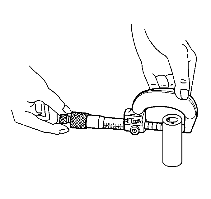
- To determine piston pin-to-bore clearance
use a micrometer and measure the piston pin.
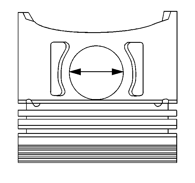
- To determine piston pin-to-bore clearance,
use an inside micrometer and measure the piston pin bore.
- To determine the piston pin-to-bore clearance, subtract the piston
pin diameter from the piston pin bore diameter. Refer to
Engine Mechanical Specifications
.

- Measure the piston with a micrometer
at a right angle to the piston pin bore, measure the piston at 11 mm
(0.433 in) from the bottom of the skirt. Refer to
Engine Mechanical Specifications
.
If the piston is not within specifications, replace the piston and pin
as an assembly.

- Inspect the connecting rod for an out-of-round
bearing bore. Refer to
Engine Mechanical Specifications
.

- Inspect the connecting rod for twisting.
- Inspect the connecting rod for damage to the bearing cap and bolt
threads.

- Measure the piston compression ring end
gap.
| | Important: Fit each compression ring to the cylinder in which it will be used.
|
| 19.1. | Place the compression ring into the cylinder bore. |
| 19.2. | Push the compression ring into the cylinder bore to approximately
6.5 mm (0.25 in) above the ring travel. |
The ring must be square to the cylinder wall.
| 19.3. | Use a feeler gage in order to measure the end gap. |


