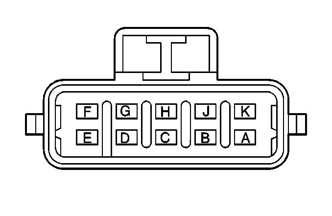
| Table 1: | Cruise Control Module |
| Table 2: | Stoplamp Switch (C1) |
| Table 3: | Cruise Control (Clutch) Switch |
| Table 4: | Cruise Control Release (Brake) Switch (Automatic Transmission) |
| Table 5: | Cruise Control Release (Brake) Switch (Manual Transmission) |
| Table 6: | Throttle Actuator Control |
| Table 7: | Throttle Actuator Control Module |

| |||||||
|---|---|---|---|---|---|---|---|
Connector Part Information |
| ||||||
Pin | Wire Color | Circuit No. | Function | ||||
A | GRY | 397 | Cruise Control On Switch Signal | ||||
B | DK BLU | 84 | Cruise Control Set/Coast Switch Signal | ||||
C | GRY/BLK | 87 | Cruise Control Resume/Accel Switch Signal | ||||
D | BRN | 86 | Cruise Control Release Signal | ||||
E | BLK | 1650 | Ground | ||||
F | PNK | 139 | Ignition 1 Voltage | ||||
G | LT BLU | 20 | Stop Lamp Supply Voltage | ||||
H | DK GRN | 83 | Cruise Control Inhibit Signal | ||||
J | WHT | 85 | Cruise Control Engaged Signal | ||||
K | DK GRN/WHT | 817 | Vehicle Speed Signal | ||||

| |||||||
|---|---|---|---|---|---|---|---|
Connector Part Information |
| ||||||
Pin | Wire Color | Circuit No. | Function | ||||
A | ORN | 140 | Battery Positive Voltage | ||||
B | LT BLU | 20 | Stop Lamp Supply Voltage | ||||

| |||||||
|---|---|---|---|---|---|---|---|
Connector Part Information |
| ||||||
Pin | Wire Color | Circuit No. | Function | ||||
A | BRN/WHT | 379 | CPP Switch Signal | ||||
B | PNK | 139 | Ignition 1 Voltage | ||||
C | GRY | 48 | CPP Switch Signal | ||||
D | BLK/WHT | 451 | Ground | ||||

| |||||||
|---|---|---|---|---|---|---|---|
Connector Part Information |
| ||||||
Pin | Wire Color | Circuit No. | Function | ||||
A | BRN | 86 | Cruise Control Release Signal | ||||
B | PNK | 139 | Ignition 1 Voltage | ||||

| |||||||
|---|---|---|---|---|---|---|---|
Connector Part Information |
| ||||||
Pin | Wire Color | Circuit No. | Function | ||||
A | BRN | 86 | Cruise Control Release Signal | ||||
B | BRN/WHT | 379 | CPP Switch Signal | ||||

| |||||||
|---|---|---|---|---|---|---|---|
Connector Part Information |
| ||||||
Pin | Wire Color | Circuit No. | Function | ||||
A | TAN | 476 | Low Reference | ||||
B | PPL | 486 | TP Sensor 2 Signal | ||||
C | GRY | 597 | 5 Volt Reference | ||||
D | BRN | 582 | Not Used | ||||
E | YEL | 581 | TAC Motor Control 1 | ||||
F | GRY/BLK | 1687 | Ignition Retard Signal | ||||
G | DK GRN | 485 | TP Sensor 1 Signal | ||||
H | TAN | 470 | Low Reference | ||||

| |||||||
|---|---|---|---|---|---|---|---|
Connector Part Information |
| ||||||
Pin | Wire Color | Circuit No. | Function | ||||
1 | YEL | 581 | TAC Motor Control - 1 | ||||
2 | -- | -- | Not Used | ||||
3 | RD/WHT | 1540 | Battery Positive Voltage | ||||
4 | -- | -- | Not Used | ||||
5 | BLK/WHT | 451 | Ground | ||||
6 | -- | -- | Not Used | ||||
7 | PNK | 339 | Ignition 1 Voltage | ||||
8 | DK BLU | 84 | Cruise Control Set/Coast Switch Signal | ||||
9 | LT BLU | 20 | Stop Lamp Supply Voltage | ||||
10 | DK GRN | 485 | TP Sensor 1 Signal | ||||
11 | GRY/BLK | 1687 | Ignition Retard Signal | ||||
12 | TAN | 470 | Low Reference | ||||
13 | BRN | 582 | TAC Motor Control - 2 | ||||
14-15 | -- | -- | Not Used | ||||
16 | ORN/BLK | 1061 | UART Serial Data [Secondary] | ||||
17 | BLK/WHT | 451 | Ground | ||||
18 | TAN | 800 | UART Serial Data [Primary] | ||||
19 | -- | -- | Not Used | ||||
20 | GRY | 397 | Cruise Control On Switch Signal | ||||
21 | GRY/BLK | 87 | Cruise Control Resume/Accel Switch Signal | ||||
22 | PPL | 486 | TP Sensor 2 Signal | ||||
23 | GRY | 597 | 5V Reference | ||||
24 | TAN | 476 | Low Reference | ||||
