
| |||||||
|---|---|---|---|---|---|---|---|
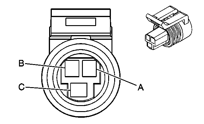
Connector Part Information |
| ||||||
Pin | Wire Color | Circuit No. | Function | ||||
A | DK GRN | 59 | A/C Compressor Clutch Supply Voltage | ||||
B | BLK | 450 | Ground | ||||
| |||||||
|---|---|---|---|---|---|---|---|
Connector Part Information |
| ||||||
Pin | Wire Color | Circuit No. | Function | ||||
A | GRY | 720 | Low Reference | ||||
B | LT BLU/BLK | 1688 | 5 Volt Reference Input | ||||
C | RED/BLK | 380 | A/C Refrigerant Pressure Sensor Signal | ||||

| |||||||
|---|---|---|---|---|---|---|---|
Connector Part Information |
| ||||||
Pin | Wire Color | Circuit No. | Function | ||||
A | BRN/WHT | 633 | CMP Sensor Signal | ||||
B | ORN/BLK | 645 | Low Reference | ||||
C | WHT/BLK | 644 | 10 Volt Reference | ||||

| |||||||
|---|---|---|---|---|---|---|---|
Connector Part Information |
| ||||||
Pin | Wire Color | Circuit No. | Function | ||||
A | LT BLU/WHT | 1800 | CKP Sensor 2 Signal | ||||
B | YEL | 573 | CKP Sensor 1 Signal | ||||
C | ORN/BLK | 645 | Low Reference | ||||
D | WHT/BLK | 644 | 10 Volt Reference | ||||

| |||||||
|---|---|---|---|---|---|---|---|
Connector Part Information |
| ||||||
Pin | Wire Color | Circuit No. | Function | ||||
A | WHT | 423 | IC Timing Control | ||||
B | TAN/BLK | 424 | IC Timing Signal | ||||
C | LT BLU/BLK | 647 | Medium Resolution Engine Speed Signal | ||||
D | PPL/WHT | 430 | Low Resolution Engine Speed Signal | ||||
E | -- | -- | Not Used | ||||
F | TAN | 630 | Camshaft Position Signal | ||||
G | YEL | 573 | CKP Sensor 1 Signal | ||||
H | LT BLU/WHT | 1800 | CKP Sensor 2 Signal | ||||
J | BRN/WHT | 633 | CMP Signal Sensor | ||||
K | BLK | 450 | Ground | ||||
L | ORN/BLK | 453 | Low Reference | ||||
M | RED/BLK | 645 | Low Reference | ||||
N | WHT/BLK | 644 | 10 Volt Reference | ||||
P | PNK | 239 | Ignition 1 Voltage | ||||

| |||||||
|---|---|---|---|---|---|---|---|
Connector Part Information |
| ||||||
Pin | Wire Color | Circuit No. | Function | ||||
A | BRN | 718 | Low Reference | ||||
B | YEL | 410 | ECT Sensor Signal | ||||
| |||||||
|---|---|---|---|---|---|---|---|
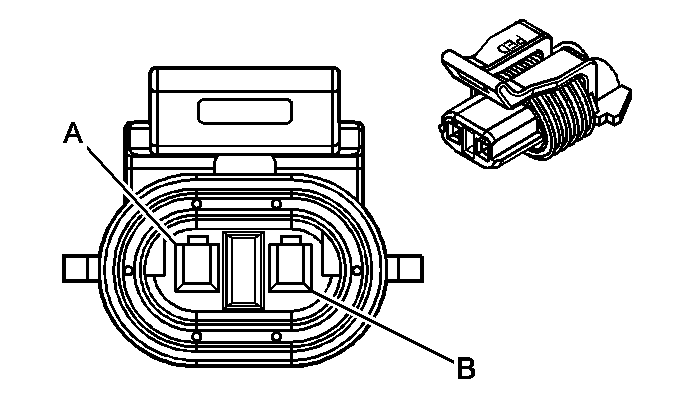
Connector Part Information |
| ||||||
Pin | Wire Color | Circuit No. | Function | ||||
A | BLK/WHT | 451 | Ground | ||||
B | BRN | 1174 | Oil Level Switch Signal | ||||

| |||||||
|---|---|---|---|---|---|---|---|
Connector Part Information |
| ||||||
Pin | Wire Color | Circuit No. | Function | ||||
A | TAN | 31 | Oil Pressure Indicator Control | ||||
B | BLK/WHT | 451 | Ground | ||||
C-D | -- | -- | Not Used | ||||

| |||||||
|---|---|---|---|---|---|---|---|
Connector Part Information |
| ||||||
Pin | Wire Color | Circuit No. | Function | ||||
A | PNK | 239 | Ignition 1 Voltage | ||||
B | DK GRN/WHT | 428 | EVAP Canister Purge Solenoid Control | ||||

| |||||||
|---|---|---|---|---|---|---|---|
Connector Part Information |
| ||||||
Pin | Wire Color | Circuit No. | Function | ||||
A | PNK | 239 | Ignition 1 Voltage | ||||
B | WHT | 1310 | EVAP Canister Vent Solenoid Control | ||||

| |||||||
|---|---|---|---|---|---|---|---|
Connector Part Information |
| ||||||
Pin | Wire Color | Circuit No. | Function | ||||
A | GRY | 435 | EGR Solenoid Control | ||||
B | TAN | 552 | Low Reference | ||||
C | BRN | 1456 | EGR Valve Position Signal | ||||
D | GRY | 598 | 5 Volt Reference | ||||
E | LT BLU | 697 | EGR Valve Supply Voltage | ||||

| |||||||
|---|---|---|---|---|---|---|---|
Connector Part Information |
| ||||||
Pin | Wire Color | Circuit No. | Function | ||||
A | PNK | 639 | Ignition 1 Voltage | ||||
B | TAN | 1744 | Fuel Injector 1 Control | ||||

| |||||||
|---|---|---|---|---|---|---|---|
Connector Part Information |
| ||||||
Pin | Wire Color | Circuit No. | Function | ||||
A | PNK | 639 | Ignition 1 Voltage | ||||
B | LT GRN/BLK | 1745 | Fuel Injector 2 Control | ||||

| |||||||
|---|---|---|---|---|---|---|---|
Connector Part Information |
| ||||||
Pin | Wire Color | Circuit No. | Function | ||||
A | PNK | 639 | Ignition 1 Voltage | ||||
B | PNK/BLK | 1746 | Fuel Injector 3 Control | ||||

| |||||||
|---|---|---|---|---|---|---|---|
Connector Part Information |
| ||||||
Pin | Wire Color | Circuit No. | Function | ||||
A | PNK | 639 | Ignition 1 Voltage | ||||
B | LT BLU/BLK | 844 | Fuel Injector 4 Control | ||||

| |||||||
|---|---|---|---|---|---|---|---|
Connector Part Information |
| ||||||
Pin | Wire Color | Circuit No. | Function | ||||
A | PNK | 639 | Ignition 1 Voltage | ||||
B | TAN/WHT | 845 | Fuel Injector 5 Control | ||||

| |||||||
|---|---|---|---|---|---|---|---|
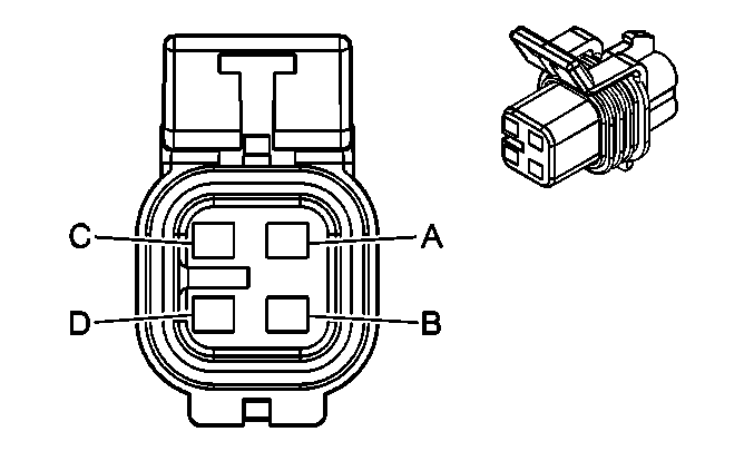
Connector Part Information |
| ||||||
Pin | Wire Color | Circuit No. | Function | ||||
A | PNK | 639 | Ignition 1 Voltage | ||||
B | YEL/BLK | 846 | Fuel Injector 6 Control | ||||
| |||||||
|---|---|---|---|---|---|---|---|
Connector Part Information |
| ||||||
Pin | Wire Color | Circuit No. | Function | ||||
A | PPL | 30 | Fuel Level Sensor Signal | ||||
B | GRY | 120 | Fuel Pump Supply Voltage | ||||
C | BLK | 150 | Ground | ||||
D | BLK/WHT | 651 | Ground | ||||
| |||||||
|---|---|---|---|---|---|---|---|
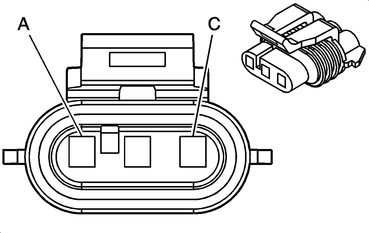
Connector Part Information |
| ||||||
Pin | Wire Color | Circuit No. | Function | ||||
A | ORN/BLK | 469 | Low Reference | ||||
B | DK GRN | 890 | Fuel Tank Pressure Sensor Signal | ||||
C | GRY | 416 | 5 Volt Reference | ||||

| |||||||
|---|---|---|---|---|---|---|---|
Connector Part Information |
| ||||||
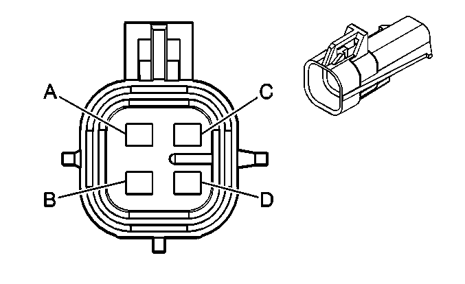
Pin | Wire Color | Circuit No. | Function | ||||
A | TAN /WHT | 1653 | HO2S Low Signal [Bank1 Sensor 1] | ||||
B | PPL/WHT | 1665 | HO2S High Signal [Bank 1 Sensor 1] | ||||
C | BLK | 450 | Ground | ||||
D | PNK | 539 | Ignition 1 Voltage | ||||
| |||||||
|---|---|---|---|---|---|---|---|
Connector Part Information |
| ||||||
Pin | Wire Color | Circuit No. | Function | ||||
A | GRY | 1981 | HO2S Low Signal [Bank 1 Sensor 2] | ||||
B | DK BLU | 1980 | HO2S High Signal [Bank 1 Sensor 2] | ||||
C | BLK | 450 | Ground | ||||
D | PNK | 539 | Ignition 1 Voltage | ||||

| |||||||
|---|---|---|---|---|---|---|---|
Connector Part Information |
| ||||||
Pin | Wire Color | Circuit No. | Function | ||||
A | TAN | 1667 | HO2S Low Signal [Bank 2 Sensor 1] | ||||
B | PPL | 1666 | HO2S High Signal [Bank 2 Sensor 1] | ||||
C | BLK | 450 | Ground | ||||
D | PNK | 539 | Ignition 1 Voltage | ||||
| |||||||
|---|---|---|---|---|---|---|---|
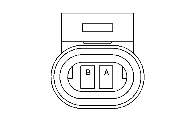
Connector Part Information |
| ||||||
Pin | Wire Color | Circuit No. | Function | ||||
A | PPL | 719 | Low Reference | ||||
B | TAN | 472 | IAT Sensor Signal | ||||
| |||||||
|---|---|---|---|---|---|---|---|
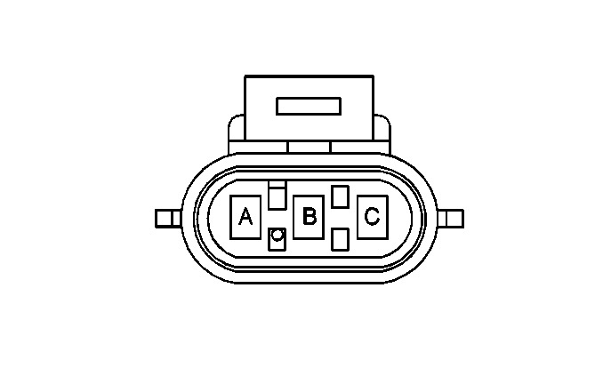
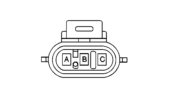
Connector Part Information |
| ||||||
Pin | Wire Color | Circuit No. | Function | ||||
A | ORN/BLK | 469 | Low Reference | ||||
B | LT GRN | 432 | MAP Sensor Signal | ||||
C | GRY | 598 | 5 Volt Reference | ||||
| |||||||
|---|---|---|---|---|---|---|---|
Connector Part Information |
| ||||||
Pin | Wire Color | Circuit No. | Function | ||||
A | YEL | 492 | MAF Sensor Signal | ||||
B | BLK/WHT | 451 | Ground | ||||
C | PNK | 539 | Ignition 1 Voltage | ||||
| |||||||
|---|---|---|---|---|---|---|---|
Connector Part Information |
| ||||||
Pin | Wire Color | Circuit No. | Function | ||||
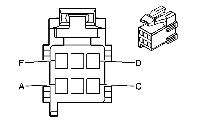
A | PPL/WHT | 1572 | Service Traction System Indicator Control | ||||
B | PNK | 39 | Ignition 1 Voltage | ||||
C | GRY | 8 | Instrument Panel Lamp Supply Voltage 1 | ||||
D | -- | -- | Not Used | ||||
E | BRN/WHT | 1571 | Traction Control Switch Signal | ||||
F | BLK/WHT | 451 | Ground | ||||

| |||||||
|---|---|---|---|---|---|---|---|
Connector Part Information |
| ||||||
Pin | Wire Color | Circuit No. | Function | ||||
A | TAN | 476 | Low Reference | ||||
B | PPL | 486 | TP Sensor 2 Signal | ||||
C | GRY | 597 | 5 Volt Reference | ||||
D | BRN | 582 | Not Used | ||||
E | YEL | 581 | TAC Motor Control 1 | ||||
F | GRY/BLK | 1687 | Ignition Retard Signal | ||||
G | DK GRN | 485 | TP Sensor 1 Signal | ||||
H | TAN | 470 | Low Reference | ||||

| |||||||
|---|---|---|---|---|---|---|---|
Connector Part Information |
| ||||||
Pin | Wire Color | Circuit No. | Function | ||||
1 | YEL | 581 | TAC Motor Control - 1 | ||||
2 | -- | -- | Not Used | ||||
3 | RD/WHT | 1540 | Battery Positive Voltage | ||||
4 | -- | -- | Not Used | ||||
5 | BLK/WHT | 451 | Ground | ||||
6 | -- | -- | Not Used | ||||
7 | PNK | 339 | Ignition 1 Voltage | ||||
8 | DK BLU | 84 | Cruise Control Set/Coast Switch Signal | ||||
9 | LT BLU | 20 | Stop Lamp Supply Voltage | ||||
10 | DK GRN | 485 | TP Sensor 1 Signal | ||||
11 | GRY/BLK | 1687 | Ignition Retard Signal | ||||
12 | TAN | 470 | Low Reference | ||||
13 | BRN | 582 | TAC Motor Control - 2 | ||||
14-15 | -- | -- | Not Used | ||||
16 | ORN/BLK | 1061 | UART Serial Data [Secondary] | ||||
17 | BLK/WHT | 451 | Ground | ||||
18 | TAN | 800 | UART Serial Data [Primary] | ||||
19 | -- | -- | Not Used | ||||
20 | GRY | 397 | Cruise Control On Switch Signal | ||||
21 | GRY/BLK | 87 | Cruise Control Resume/Accel Switch Signal | ||||
22 | PPL | 486 | TP Sensor 2 Signal | ||||
23 | GRY | 597 | 5 Volt Reference | ||||
24 | TAN | 476 | Low Reference | ||||

| |||||||
|---|---|---|---|---|---|---|---|
Connector Part Information |
| ||||||
Pin | Wire Color | Circuit No. | Function | ||||
A | PPL | 401 | VSS Low Signal | ||||
B | YEL | 400 | VSS High Signal | ||||
