For 1990-2009 cars only
Cylinder Head Assemble 6.2L LS9
Special Tools
J 8062 Valve Spring Compressor - Head Off
For equivalent regional tools, refer to Special Tools
- Clean the cylinder head valve spring shim area.
- Install the valves (228) into the proper port. Refer to Separating Parts.
- Install the valve stem oil seal (222).
- Install the valve spring (223).
- Install the valve spring cap (224).
- Using the J 8062 compressor , compress the valve spring.
- Install the valve stem keys.
- Install the remaining valves, springs, and other components.
- Install sealant GM P/N 12346004 (Canadian P/N 10953480), or equivalent, to the threads of the coolant temperature sensor (725).
- Install the coolant temperature sensor into the left cylinder head and tighten to 20 N·m (15 lb ft).
- Install sealant GM P/N 12346004 (Canadian P/N 10953480), or equivalent, to the threads of the cylinder head plug (229).
- Install the cylinder head plug to the right cylinder head and tighten to 20 N·m (15 lb ft).
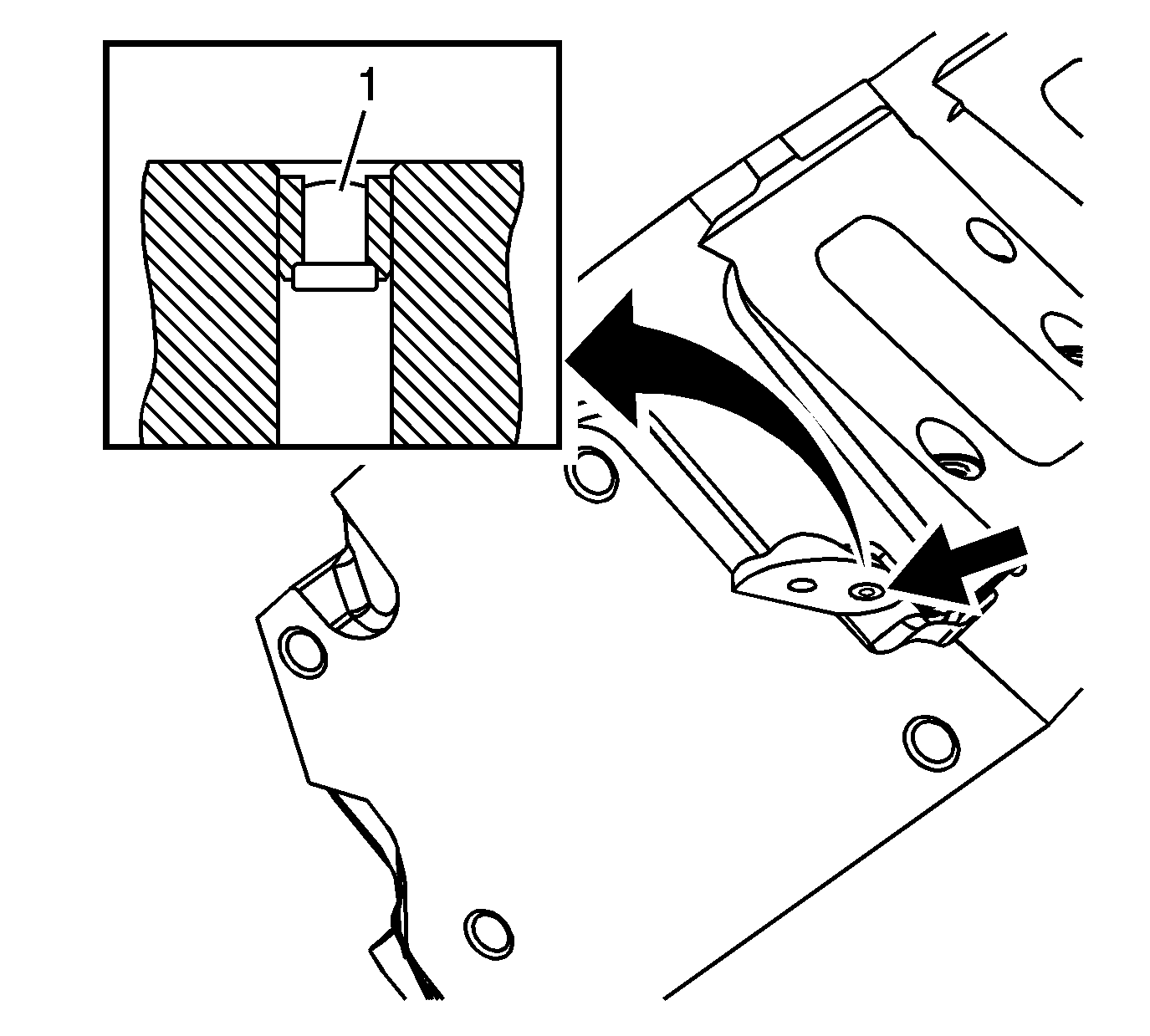
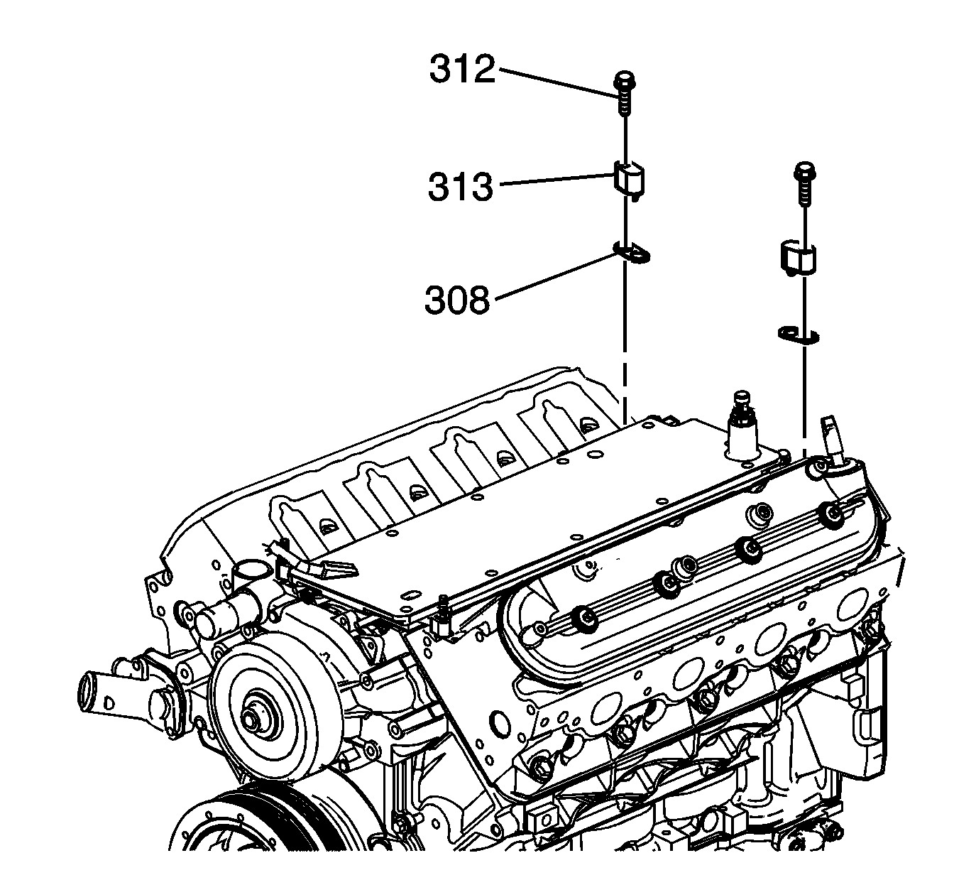
- Production applications use a rivet-type plug at the top rear coolant passage of each cylinder head. If service of a leaking plug is required, it is necessary to remove the cylinder head from the engine to properly remove the plug. Refer to Cylinder Head Disassemble.
- If plug removal is required, install a first design coolant air bleed cover and bolt to complete the repair.
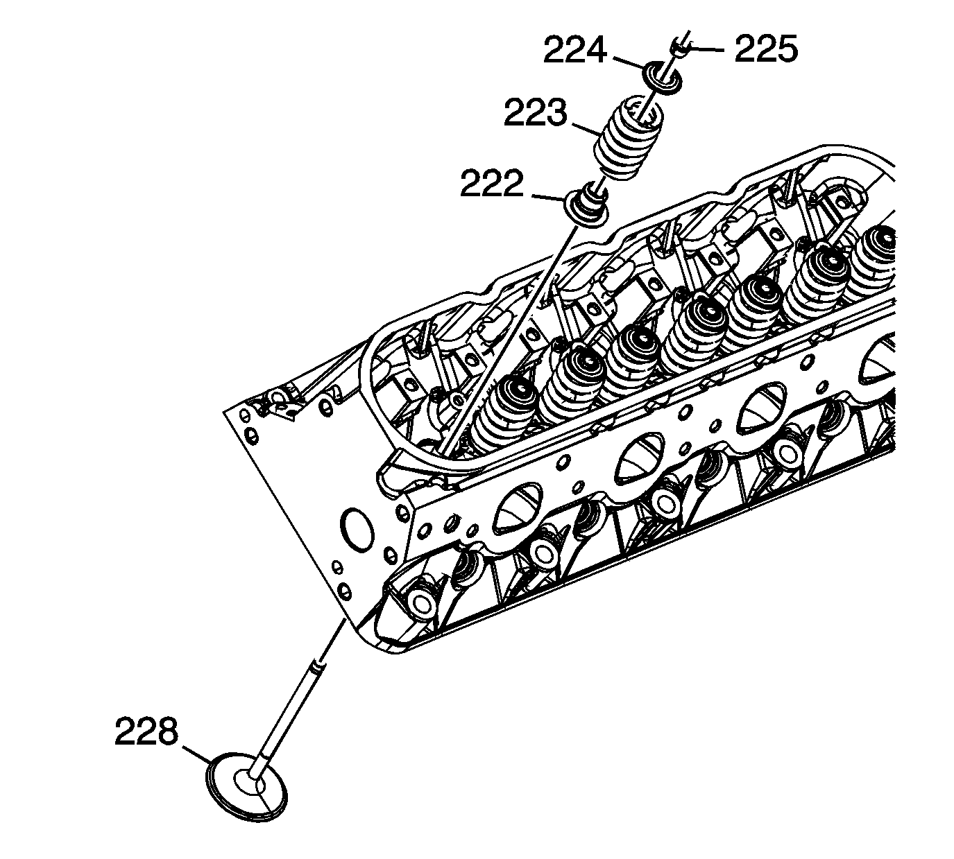
Note: When using the valves and related components again, install the parts to their original location.
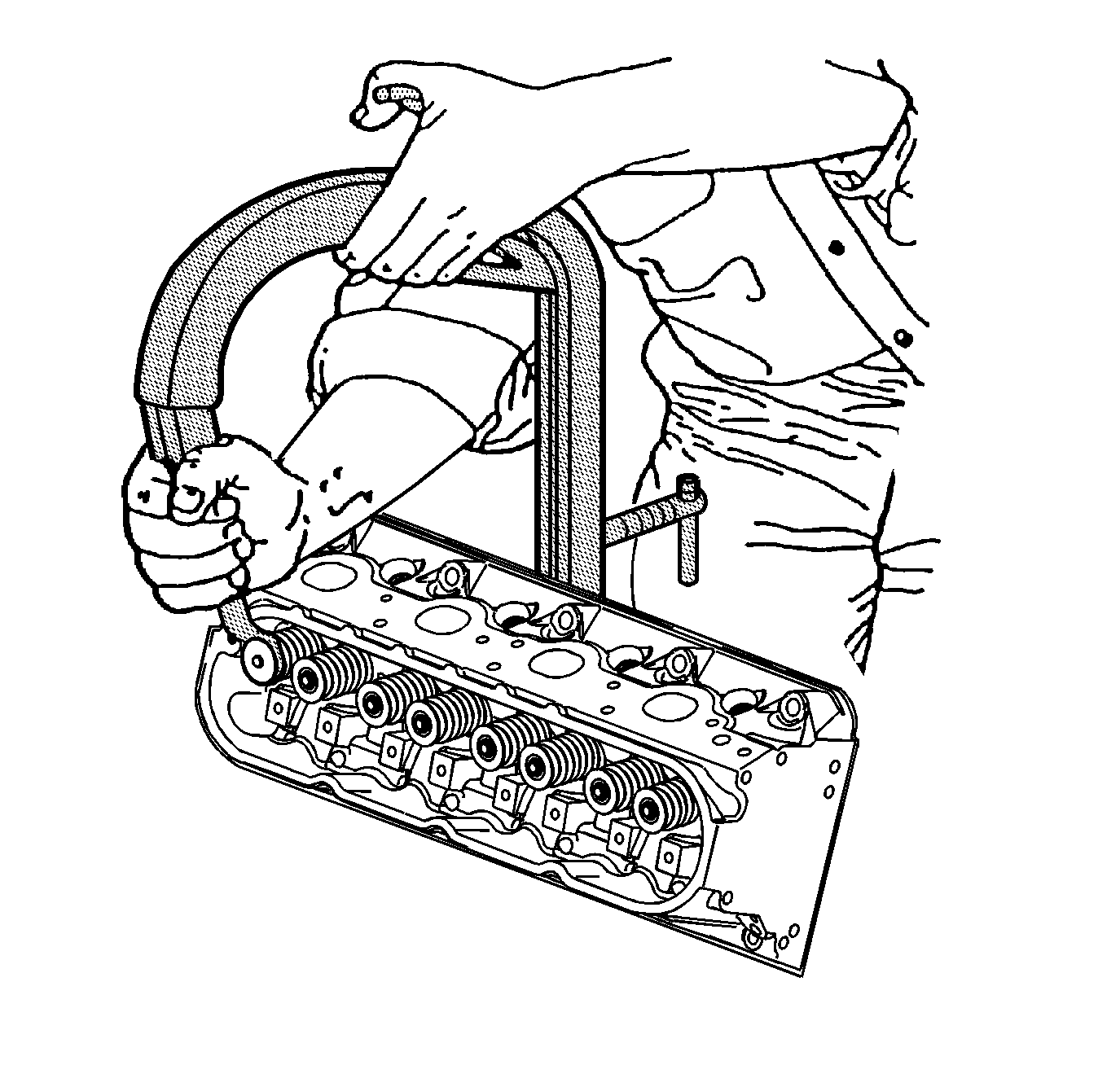
| 7.1. | Use grease in order to hold the keys in place and remove the J 8062 compressor . |
| 7.2. | Ensure the keys seat properly in the groove of the valve stem. |
| 7.3. | Tap the end of the valve stem with a plastic face hammer to seat the keys, if necessary. |
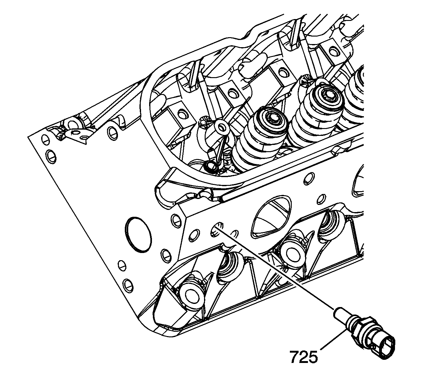
Caution: Refer to Fastener Caution in the Preface section.
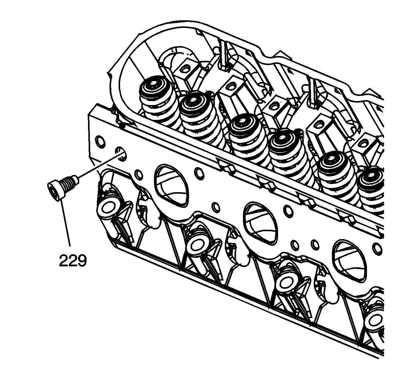
Cylinder Head Assemble 6.2L LS3
Special Tools
J 8062 Valve Spring Compressor - Head Off
For equivalent regional tools, refer to Special Tools
- Clean the cylinder head valve spring shim area.
- Install the valves (228) into the proper port. Refer to Separating Parts.
- Install the valve stem oil seal (222).
- Install the valve spring (223).
- Install the valve spring cap (224).
- Using the 8062 compressor , compress the valve spring.
- Install the valve stem keys.
- Using a ruler, measure the valve spring installed height.
- Install the remaining valves, springs, and other components.
- Install sealant GM P/N 12346004 (Canadian P/N 10953480), or equivalent, to the threads of the coolant temperature sensor (725).
- Install the coolant temperature sensor into the left cylinder head and tighten to 20 N·m (15 lb ft).
- Install sealant GM P/N 12346004 (Canadian P/N 10953480), or equivalent, to the threads of the cylinder head plug (229).
- Install the cylinder head plug to the right cylinder head. and tighten to 20 N·m (15 lb ft)
- Apply threadlock GM P/N 12345382 (Canadian P/N 10953489), or equivalent, to the sides of the cylinder head plugs (216).
- Install the cylinder head plugs into the cylinder head.
- Second design applications use a rivet-type plug at the top rear coolant passage of each cylinder head. If service of a leaking plug is required, it is necessary to remove the cylinder head from the engine to properly remove the plug.
- If plug removal is required, install a first design coolant air bleed cover and bolt to complete the repair.

Note: When using the valves and related components again, install the parts to their original location.

| 7.1. | Use grease in order to hold the keys in place and remove the 8062 compressor . |
| 7.2. | Ensure the keys seat properly in the groove of the valve stem. |
| 7.3. | Tap the end of the valve stem with a plastic face hammer to seat the keys, if necessary. |
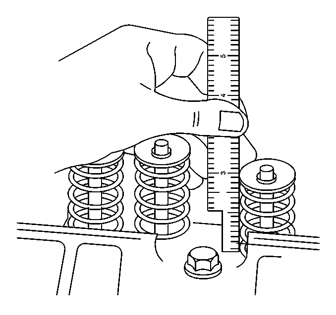
Measure from the base of the valve spring to the top of the valve spring.
Specification
| • | If the installed height exceeds 46.25 mm (1.82 in), install a valve spring shim of approximately 0.5 mm (0.02 in) thick. |
| • | Do not shim the valve spring to obtain less than the specified height. |
| Do not assemble the components without a spring shim on the cylinder head. |

Caution: Refer to Fastener Caution in the Preface section.


A properly installed plug should be installed 2.5 mm (0.1 in) below the end face of the head.


