For 1990-2009 cars only
- Remove the water manifold bolts (1).
- Remove the water manifold (2).
- Remove the water manifold gaskets (3).
- Remove the coolant pipes (2) and seals (1).
- Remove the seals (1) from the pipes (2) as required.
- Remove the charge air coolers (2), bolts (1) and insulators (3), as required.
- Remove the air outlet pressure sensor bolt (1).
- Remove the sensor (2).
- Remove the sensor seal (3), as required.
- Remove the inlet air temperature sensor (1).
- Remove the barometric pressure (BARO) sensor bolt (1).
- Remove the BARO sensor (2).
- Remove the BARO sensor seal (3), as required.
- Remove the insulator seals (1).
- Remove the charge air bypass valve tube (1).
- Remove the charge air bypass valve vacuum tube (2).
- Remove the inlet air pressure sensor bolt (1).
- Remove the inlet air pressure sensor (2).
- Remove the inlet air pressure sensor seal (3), as required.
- Loosen the evaporative emissions (EVAP) bolt.
- Remove the EVAP valve (1).
- Remove the EVAP valve seal (2), as required.
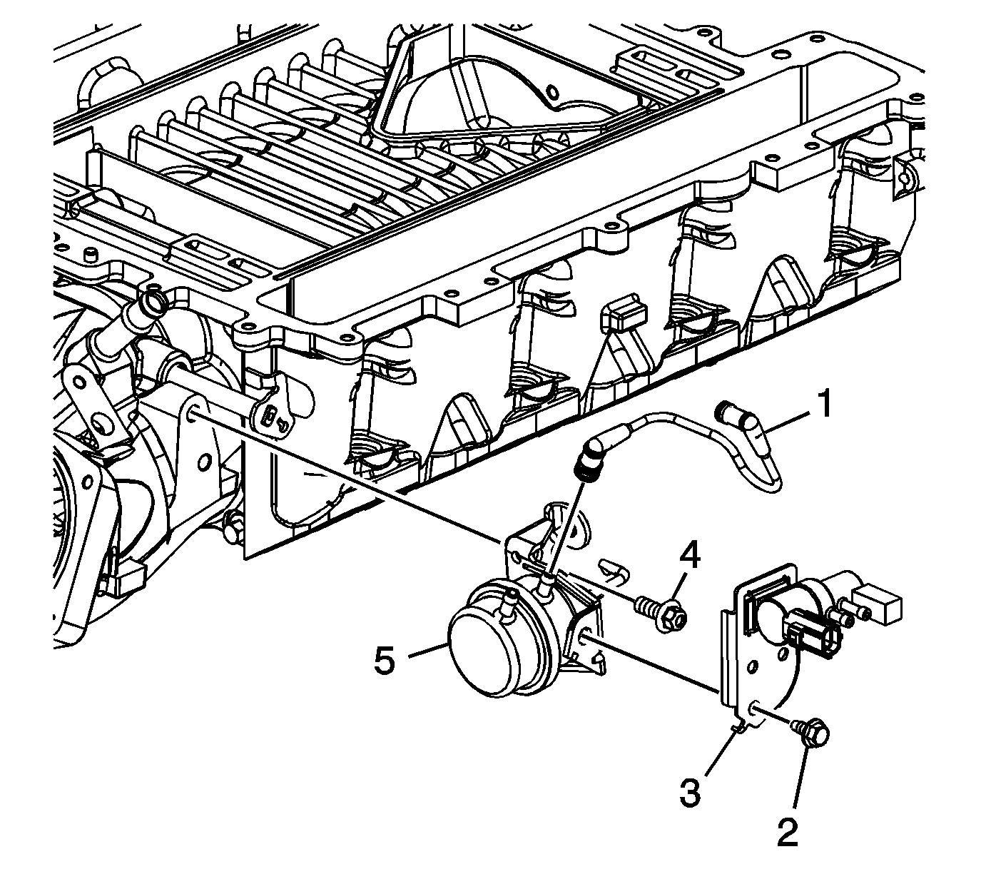
- Remove the bypass actuator tube (1).
- Remove the charge air bypass valve bolt (2).
- Remove the charge air bypass valve (3).
- Remove the bypass actuator bolts (4).
- Rotate the actuator downward and remove the rod from the lever of the supercharger.
- Remove the bypass actuator (5).
- Drill out the gasket rivets (1) using a drill bit with an outside diameter (OD) no larger than 3.2 mm (0.125 in).
- Remove the gaskets (2).


Note:
• Do not allow dirt or debris to enter the passages of the supercharger. Cover the intake ports as required. • With the manifold positioned upside down on a bench, the lower assembly may be positioned onto the intercooler cover dowel pins. Use care not to reposition or bend the dowel pins.
