Removal Procedure
Tools Required
| • | J 3289-20 Holding Fixture |
| • | J 34013-B Strut Compressing Tool |
| • | J 34013-20 Dampener Rod Clamp |
| • | J 34013-27 Alignment Rod |
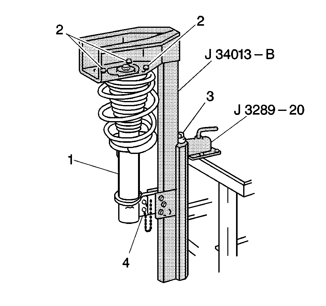
- Mount the J 34013-B and theJ 3289-20 .
- Mount the strut (1) into the J 3289-20 . Take notice that the J 34013-B has the strut mounting holes drilled for a specific car line.
- Compress the strut approximately ½ the height after the initial contact with the cap. Do not bottom the spring (1) or dampen the rod.
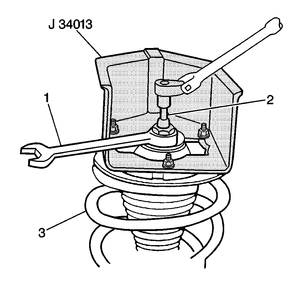
- Remove the nut (2) from the strut the dampener shaft.
- Place the J 34013-27 on top of the dampen shaft.
- Remove the components 1 through 10.
Notice: Care should be taken to avoid scratching or cracking the spring coating when handling the front suspension coil spring. Damage can cause premature failure.
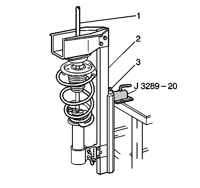
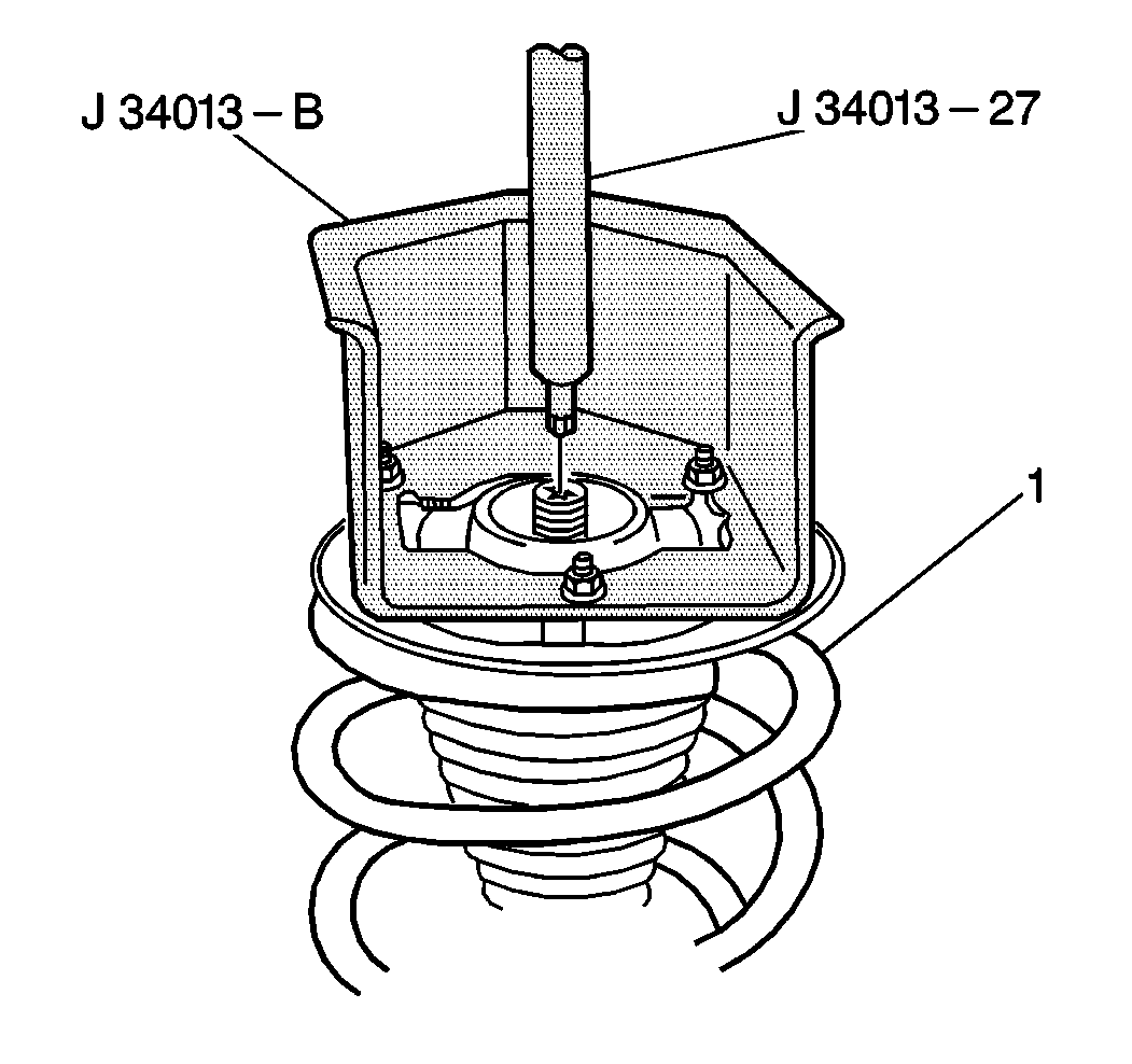
Use this rod to guide the dampen shaft straight down through the bearing cap while decompressing the spring (1).
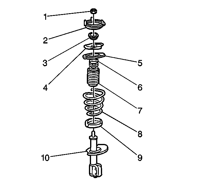
Installation Procedure
- Install the bearing cap if the cap was previously removed from the top of the strut (8).
- Mount the strut into the J 34013-B using the bottom locking pin only.
- Extend the dampener shaft (1) and install the J 34013-20 onto the dampener shaft.
- Install the spring (6) over the dampener.
- Swing the assembly up in order to install the upper locking pin (2).
- Install the upper insulator (5).
- Install the shield (10). Install the bumper (9).
- Install the upper spring seat.
- Face the upper spring seat flat in the same direction as the centerline of the strut/knuckle assembly spindle.
- Install the J 34013-27 .
- Turn the forcing screw (3) while the J 34013-27 centers the assembly.
- Remove the J 34013-27 and install the nut (2) when the threads on the dampen shaft are visible.
- Tighten the nut (2).
- Use a line wrench (1) while holding the dampen shaft with the socket.
- Remove the clamp Use the J 34013-20 .
Notice: Care should be taken to avoid scratching or cracking the spring coating when handling the front suspension coil spring. Damage can cause premature failure.

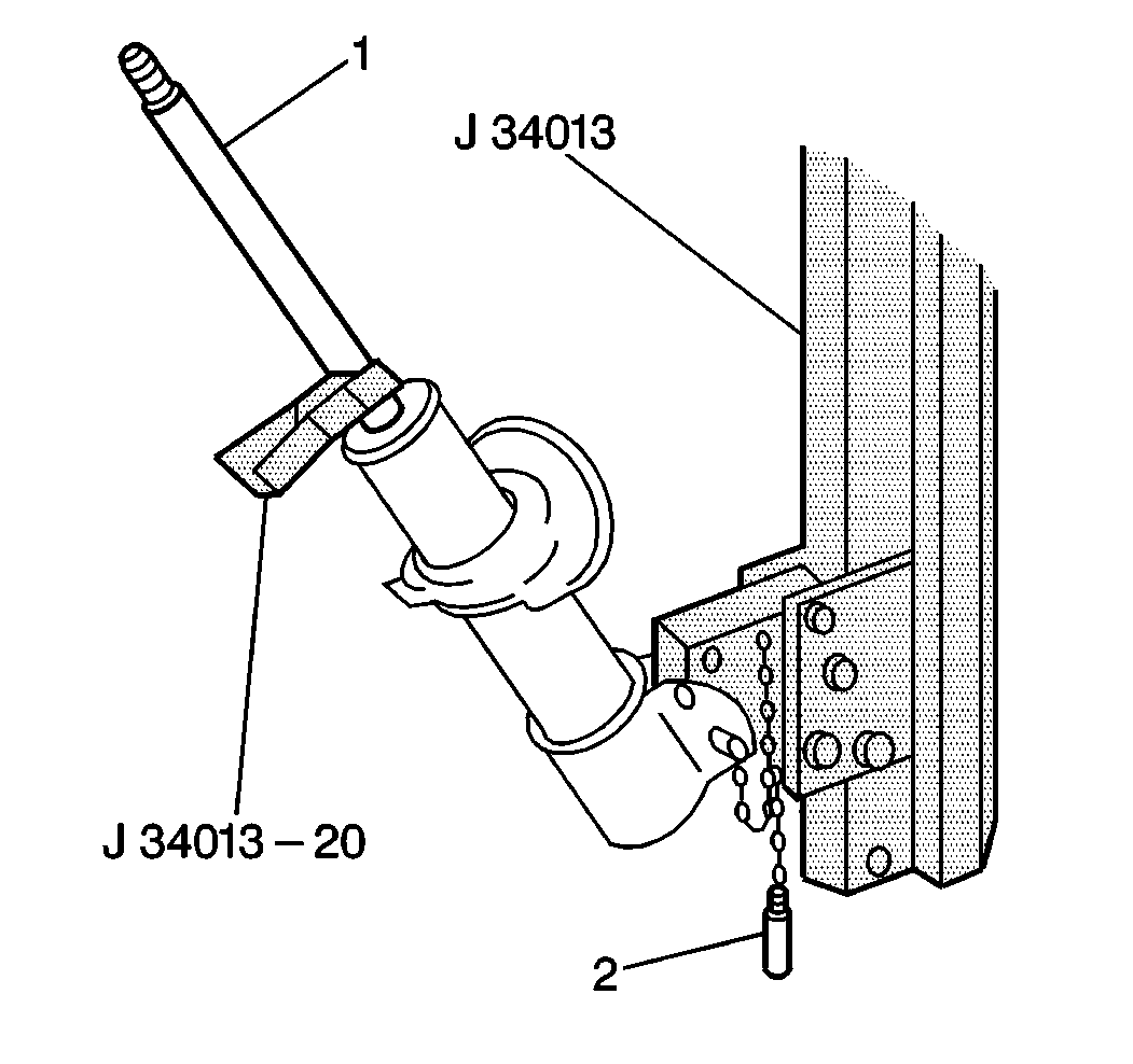


Important: The flat on the lower spring seat is NOT perpendicular to the strut/knuckle opening.

Notice: Use the correct fastener in the correct location. Replacement fasteners must be the correct part number for that application. Fasteners requiring replacement or fasteners requiring the use of thread locking compound or sealant are identified in the service procedure. Do not use paints, lubricants, or corrosion inhibitors on fasteners or fastener joint surfaces unless specified. These coatings affect fastener torque and joint clamping force and may damage the fastener. Use the correct tightening sequence and specifications when installing fasteners in order to avoid damage to parts and systems.
Tighten
Tighten the nut to 70 N·m (52 lb ft).

