For 1990-2009 cars only
Tools Required
| • | J 3289-20 Base Plate |
| • | J 33366 Holding Fixture |
| • | J 35274 Gear Puller |
| • | J 22888-30 Puller Legs |
| • | J 22888 Puller |
| • | J 24256-A Bearing Race Remover |
| • | J 8092 Driver Handle |
| • | J 33370 Bearing Race Remover |
| • | J 26941 Puller |
| • | J 33367 Puller Bridge |
| • | J 37245 Bushing Remover |
| • | J 36190 Universal Driver Handle |
| • | J 37158 Bearing Remover |
- Remove the clutch release bearing.
- Remove the rear cover bolts and the rear cover assembly from the transaxle case.
- Remove the control box bolts and the control box assembly from the transaxle case.
- Shift the transaxle into gear using a screwdriver.
- Remove the crimps in the 5th speed drive and driven gear retaining nuts using a hammer and a punch.
- Remove the retaining nuts from the input and output shaft.
- Discard the retaining nuts.
- Shift the transaxle into neutral.
- Align the detents on the shift rails.
- Remove the detent spring retaining bolts, the detent springs and the detent balls for the following gears:
- Remove the reverse detent spring retaining bolts, the detent spring and the detent ball.
- Put the 5th gear synchronizer in neutral.
- Remove the 5th gear shift fork roll pin.
- Discard the roll pin.
- Remove the following 5th gear components from the output shaft as an assembly:
- Remove the 5th speed gear from the input shaft using the J 35950 and the J 35274-A .
- Remove the screws with Torx™ (No. 45) from the bearing retainer.
- Remove the bearing retainer and the snap ring from the output shaft.
- Remove the shim from the output shaft.
- Remove the reverse idler shaft bolt at the transaxle case.
- Remove the following items from the output shaft using the J 22888 and the J 22888-30 :
- Remove the snap ring from the input bearing groove.
- Remove the transaxle case bolts.
- Separate the transaxle case from the clutch housing.
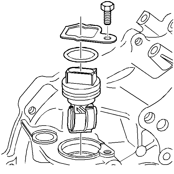
- Remove the backup lamp switch.
- Remove the reverse shift shaft snap ring (3).
- Pull up on the shaft until the interlock pin aligns with the reverse shift shaft detent (approximately ¼-½ inch).
- Remove the 5th shift shaft (1).
- Remove the reverse shift shaft (2).
- Remove the reverse idle gear.
- Remove the reverse idle shaft indexing pin.
- Remove the roll pin (1) from the 1st/2nd shift fork using a punch and hammer.
- Discard the roll pin.
- Slide the 1st/2nd shaft upward and clear of the housing.
- Remove the fork and the shaft from the case.
- Remove the reverse shift lever clevis pin.
- Remove the reverse shift lever pin.
- Remove the reverse shift lever.
- Remove the input and output shafts with the 3rd/4th shift fork and shaft as an assembly.
- Remove the reverse shift bracket together with the four bolts.
- Remove the three 10 mm interlock pins. The pin lengths are specific for this location.
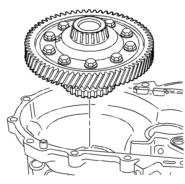
- Remove the differential case assembly from the clutch housing.
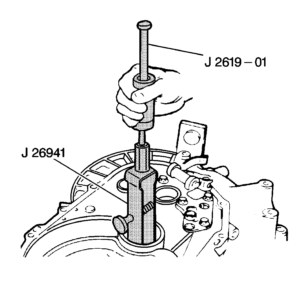
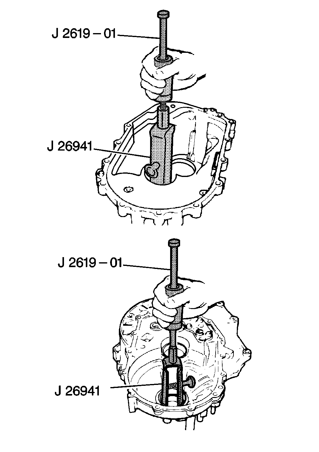
- Remove the outer races for the output shaft front. Use the J 26941 and the J 2619-O1 .
- Remove the differential side bearing from the clutch housing. Use the J 26941 and the J 2619-O1 .
- Remove the input shaft front bearing from the clutch housing. Use the J 41678 and the J 8092 .
- Remove the input shaft seal from the housing.
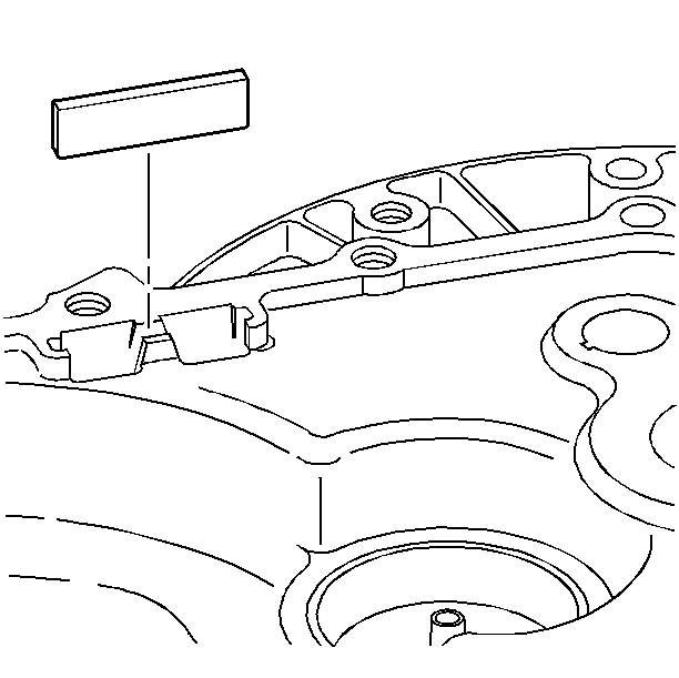
- Remove the magnet from the clutch housing.
- Remove the bolt and vehicle speed sensor from the clutch housing.
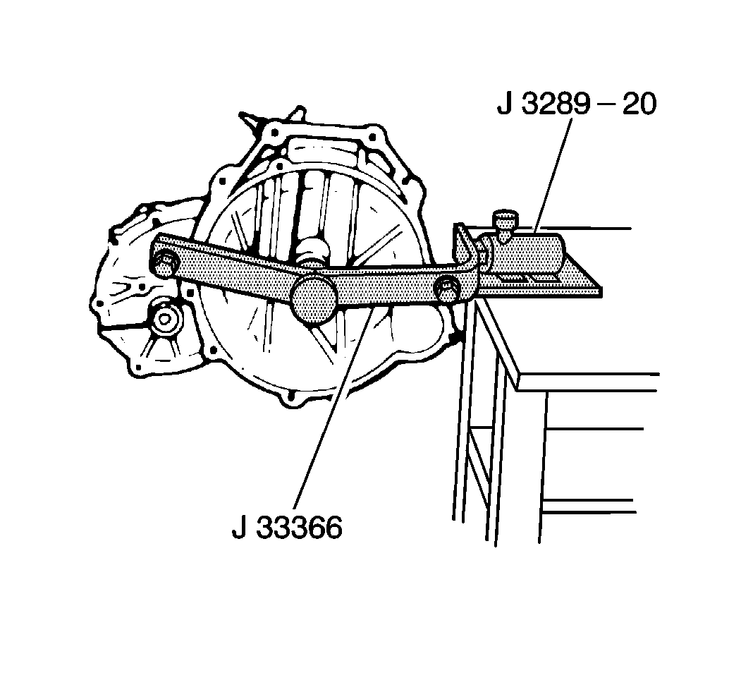
| • | Attach the transaxle to the J 33366 . |


| • | The 1st/2nd gear (1) |
| • | The 3rd/4th gear (2) |
| • | The 5th gear (3) |

| • | The synchronizer hub |
| • | The sleeve |
| • | The roller bearing |
| • | The shift fork and gear |


| • | The collar |
| • | The thrust washer |
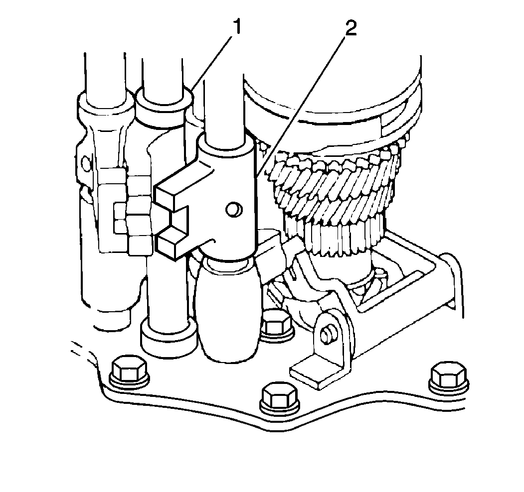
Important: The detent pin is located at the bottom of the 5th shift shaft. The detent pin is specific for the 5th shift shaft, do not lose the detent pin.


Important: Do not lose the interlock pin located at the bottom of the 3rd/4th shift shaft. The pins are specific for each shaft.
