Caution: Unless directed otherwise, the ignition and start switch must be in the OFF or LOCK position, and all electrical loads must be OFF before servicing
any electrical component. Disconnect the negative battery cable to prevent an electrical spark should a tool or equipment come in contact with an exposed electrical terminal. Failure to follow these precautions may result in personal injury and/or damage to
the vehicle or its components.
- Disconnect
the negative battery cable.
- Drain and recover the coolant. Refer to
Cooling System Draining and Filling
in Engine Cooling.
- Remove the throttle body to the air cleaner duct.
- Remove the heater inlet and throttle body hose from the water
outlet.
- Remove the power brake vacuum hose from the throttle body.
- Remove the following electrical connections:
| • | Intake Air Temperature (IAT) sensor. |
| • | EVAP Canister Purge solenoid. |
| • | Camshaft position sensor. |
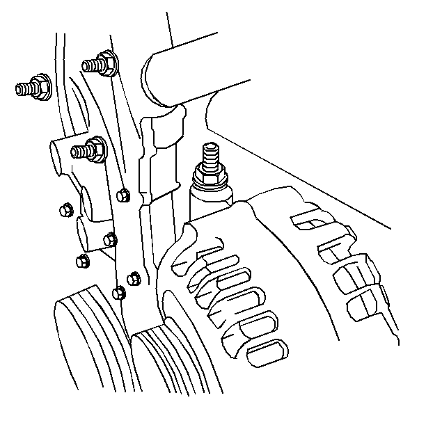
- Remove the generator stud-ended
bolt.
- Remove the intake manifold brace.
- Remove the intake manifold. Refer to
Intake Manifold Replacement
.
- Install the generator stud-ended bolt.
- Install the J 28467-360
and J 28467-400 in order to support the engine.
- Remove the exhaust manifold. Refer to
Exhaust Manifold Replacement
.
- Remove the ignition coil and module assembly electrical connections.
- Remove the ignition coil and the module assembly to the camshaft
housing bolts. Remove the assembly by pulling it straight up.
- Use the J 36011
to
remove the connector assembly if it is stuck to the spark plugs. Use the tool
by first twisting then pulling up on the connector assembly.
- Disconnect the camshaft position sensor connector.
- Remove the power steering pump. Refer to
Power Steering Pump Replacement
in Power
Steering System.
- Disconnect the vacuum line from the fuel pressure regulator and
the fuel injector harness connector.
- Remove the fuel line retaining clamp from the bracket on top of
the intake camshaft housing.
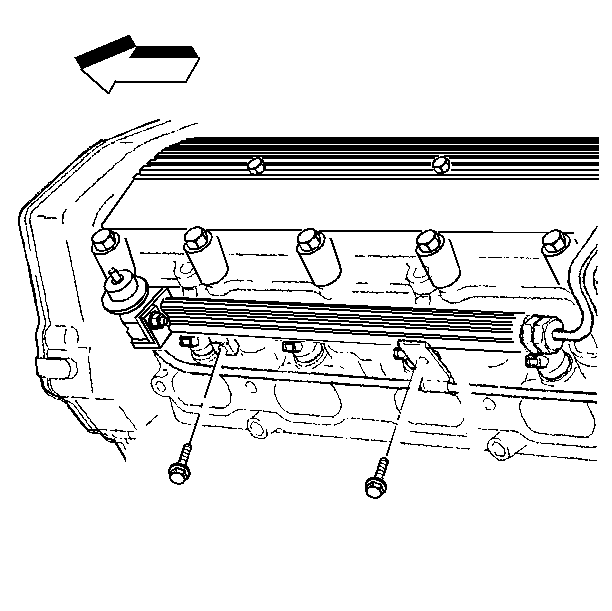
- Remove the fuel rail to
the camshaft housing retaining bolts.
- Use the following procedure in order to remove the fuel rail from
the cylinder head:
| 21.1. | Cover the injector openings in the cylinder head. |
| 21.2. | Cover the injector nozzles. |
| 21.3. | Leave the fuel lines attached and position the fuel rail aside
(on top of the master cylinder). |
- Disconnect the timing chain housing at the intake camshaft housing.
Do not remove it from the vehicle. Refer to
Timing Chain Housing Replacement
.
- Disconnect the electrical connection from the oil pressure switch.
- Remove the transmission fluid level indicator tube assembly from
the exhaust camshaft cover and position it aside (automatic transmission only).
- Remove the intake camshaft housing. Refer to
Intake Camshaft, Housing and Lifter Removal
.
- Remove the exhaust camshaft housing. Refer to
Exhaust Camshaft, Housing and Lifter Removal
.
- Disconnect the radiator inlet (upper) hose from the coolant outlet.
- Remove the coolant temperature sensor connectors.
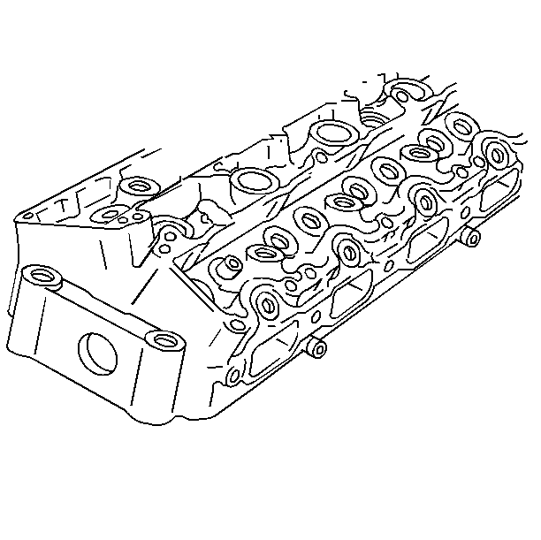
- Remove the cylinder head
to block bolts.
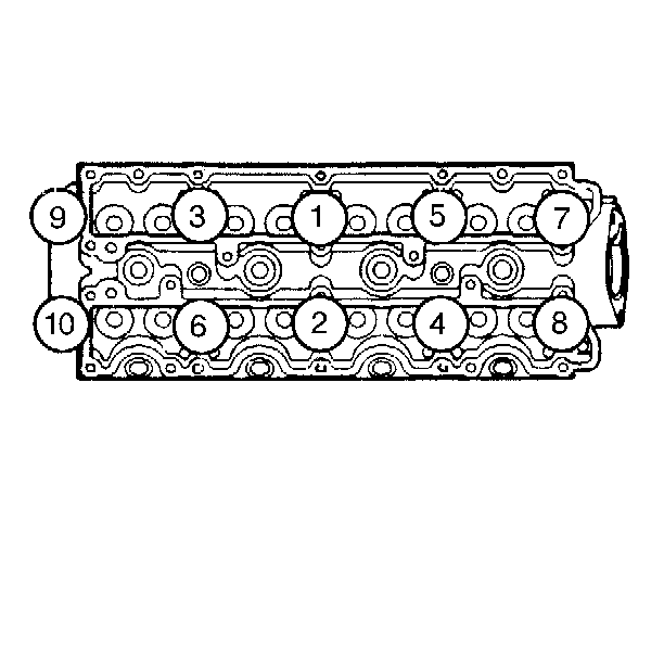
- Reverse the tightening
sequence shown in order to remove the cylinder head to block bolts.
Notice: Engine damage may result if an abrasive paper, pad, or motorized wire
brush is used to clean any engine gasket surfaces.
Important:
| • | Use a razor blade gasket scraper in order to clean the cylinder
head and the cylinder block gasket surfaces. Do not gouge or scratch the gasket
surfaces or the combustion chamber surfaces. Use a new razor blade for each
cylinder head and the cylinder block. |
| • | Hold the gasket scraper so the blade is as parallel to the gasket
surface as possible. |
| • | The feel of the gasket surface is important, not the appearance.
There will be indentations from the gasket left in the cylinder head after
all of the gasket material is removed. These small indentations will be
filled in by the new gasket. |
| • | Do not use any other method or technique to clean the gasket surfaces. |
| • | Do not use a tap to clean the cylinder head bolt holes. Use a
nylon bristle brush. |
- Clean the old sealer/lube and dirt from the bolt, the studs, and the
bolt holes.
Clean the bolt holes with a nylon bristle brush.
Caution: Wear safety glasses when using compressed air in order to prevent eye
injury.
- When cleaning the cylinder head long bolt holes, use a suitable commercial
spray liquid solvent and compressed air from an extended-tip blow gun in
order to reach the bottom of the holes.
- Clean the following components:
| • | The cylinder head bolts. |
| • | Remove all the varnish, the soot, and the carbon to the bare metal. |
| • | Do not use a wire brush on any gasket sealing surface. |
| • | The remains of sealer from the plug holes. |
Important:
| • | Do not remove the spark plugs from an aluminum cylinder head until
the cylinder head has cooled. |
| • | Clean the dirt and debris from the spark plug recess area. |
| • | If the spark plug opening threads are damaged and not restorable
with a Thread Chaser, use the thread inserts in order to repair the threads. |
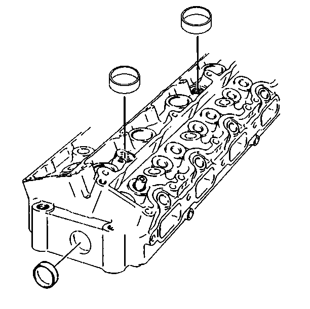
- Disassemble the following
components:
| • | Obtain a suitable self-threading screw. |
| • | Drill a hole in the plug. |
| • | Install the self-threading screw. |
- Remove the spark plugs.
- Inspect the cylinder head gasket and mating surfaces for the following
damage:
- If the gasket has failed, use the following list to determine
the cause:
| • | Loose or warped cylinder head. |
| • | Missing, off location, or not fully seated dowel pins. |
| • | Corrosion in the seal area around the coolant passages. |
| • | Chips in the cylinder head bolt holes. |
| • | Bolt holes in the cylinder block not drilled or tapped deeply
enough. |
- Inspect the cylinder head bolts for damaged threads or stretching
and damaged heads caused by an improper use of tools.
Replace any suspect bolts.
Important: Replace the cylinder head as necessary.
Do not attempt to weld the cylinder head.
- Inspect the cylinder head for cracks between the valve seats and in
the exhaust ports.
- Inspect the cylinder head deck for damage.
Replace as necessary.
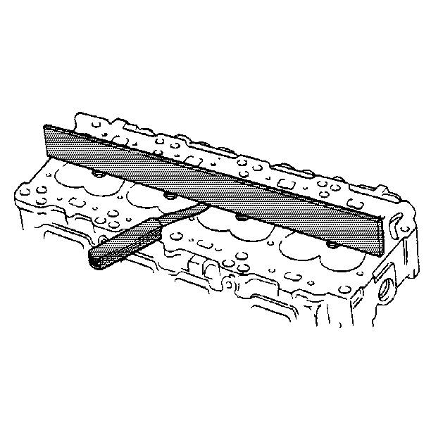
- Inspect the following
components for flatness:
| • | The cylinder head deck. |
| • | The intake manifold mating surfaces. |
| • | The exhaust manifold mating surfaces. |
- These surfaces may be reconditioned by parallel grinding.
| • | If the warpage is less than 0.076 mm (0.003 in),
reuse the cylinder head but do not resurface. |
| • | If the warpage is between 0.076 mm (0.003 in) and
0.25 mm (0.010 in), resurface the cylinder head before reusing. |
| • | If the warpage is over 0.25 mm (0.010 in), discard
the cylinder head. |
- Inspect all of the threaded holes for damage.
The threads may be reconditioned with thread inserts.
- Inspect the sealing surfaces and the cylinder head plug.
- Inspect the valve seats for excessive wear and burned spots.
| • | The valve seats may be reconditioned by grinding. An oscillation
type valve seat grinder is preferred. Follow the grinder manufacturer's instructions.
Refer to Engine Mechanical Specifications for seat angles. If after grinding,
the new seat is too wide, it may be narrowed by using a 20 degree
or 70 degree stone. The 20 degree stone will lower the seat
and the 70 degree stone will raise the seat. |
| • | Since the valve guide serves to support and center the valve grinder,
it is essential that the valve guide is cleaned properly. The valve guide
cleaning must be done before any necessary reaming. Refer to Valve Stem
Oil Seal and Valve Spring Replacement (Intake) or Valve Stem Oil Seal and
Valve Spring Replacement (Exhaust). |
Notice: In order to avoid damage, install the spark plugs after the cylinder
head has been installed on the engine.
- Assemble the cylinder head plug.
Coat the plugs with the Head Gasket Sealer GM P/N 1050026 or the equivalent.
- Assemble the valve mechanism.
Cylinder Head Installation.
- The intake camshaft housing. Refer to
Intake Camshaft, Housing and Lifter Removal
.
- The exhaust camshaft housing. Refer to
Exhaust Camshaft, Housing and Lifter Removal
.
- Install the timing chain housing and the timing chain. Refer to
Timing Chain Housing Replacement
.
- Uncover the fuel injectors.
- Install new injector O-ring seals.
- Lubricate the O-ring seals with engine oil.
- Uncover the injector openings in the cylinder head.
- Install the fuel rail onto the cylinder head.

Notice: Use the correct fastener in the correct location. Replacement fasteners
must be the correct part number for that application. Fasteners requiring
replacement or fasteners requiring the use of thread locking compound or sealant
are identified in the service procedure. Do not use paints, lubricants, or
corrosion inhibitors on fasteners or fastener joint surfaces unless specified.
These coatings affect fastener torque and joint clamping force and may damage
the fastener. Use the correct tightening sequence and specifications when
installing fasteners in order to avoid damage to parts and systems.
- Install the fuel
rail to the camshaft housing bolts and tighten to specification.
Tighten
Tighten the bolts to 26 N·m (19 lb ft).
- Install the fuel line retaining clamp and the retainer to the
bracket on top of the camshaft housing.
- Install the vacuum line to the fuel pressure regulator.
- Install the fuel injector harness connector.
- Install the camshaft position sensor connector.
Important: When reinstalling the power steering pump apply a 3 mm bead of
GM P/N 12346586 sealer or the equivalent to the joint at the end of the camshaft
housing halves before installation of the power steering pump and the pump
face seal.
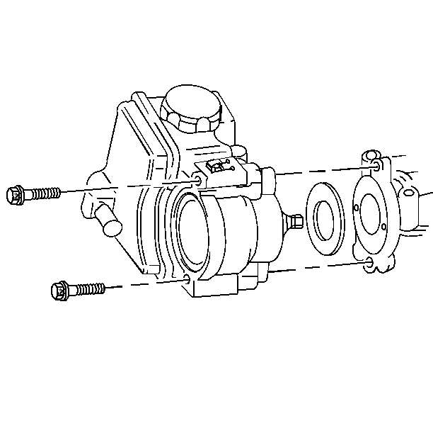
- Install the power steering
pump assembly. Refer to
Power Steering Pump Replacement
in Power Steering System.
- Install the power steering bolt.
Tighten
Tighten the bolt to 26 N·m (19 lb ft).
- Install the electrical connection from the oil pressure switch.
- For automatic transmission equipped vehicles, install the transmission
fluid level indicator tube assembly from the exhaust camshaft cover.
Position aside.
- Install the electrical connector to the ignition coil and the
module assembly.
- Reinstall any spark plug boot connector assembly that stuck to
a spark plug back onto the ignition coil and module assembly.
- Locate the ignition coil and the module assembly over the spark
plugs and push straight down.
- Clean any loose lubricant that is present on the ignition coil
and the module assembly to the camshaft housing bolts.
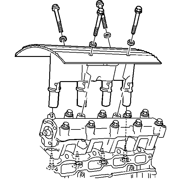
- Apply the Pipe Sealant
GM P/N 1052080 or the equivalent onto the ignition coil and the module cover
assembly to the camshaft housing bolts.
Tighten
Tighten the bolts to 15 N·m (11 lb ft) +
30 degrees.
- Install the electrical connector to the ignition coil and the
module assembly.
- Remove the J 28467-360
and the stud-ended generator bolt.
- Install the intake manifold. Refer to
Intake Manifold Replacement
.
- Connect the coolant temperature sensor connectors.
- Connect the upper radiator hose to the coolant outlet.
- Connect the following electrical connectors:
- Install the exhaust manifold. Refer to
Exhaust Manifold Replacement
.
- Install the throttle body to air cleaner duct.
- Fill the coolant system. Refer to
Cooling System Draining and Filling
in Engine Cooling.
- Connect the negative battery cable.


