Removal Procedure
Tools Required
| • | J 36660-A Torque Angle Meter |
| • | J 36011 Spark Plug Connector Assembly Remover |
- Disconnect the negative battery cable.
- Remove the ignition coil and the module assembly electrical connection.
- Remove the ignition coil and the module assembly to the camshaft housing bolts and remove the assembly by pulling straight up.
- Use the J 36011 in order to remove the connector assembly if stuck to the spark plugs.
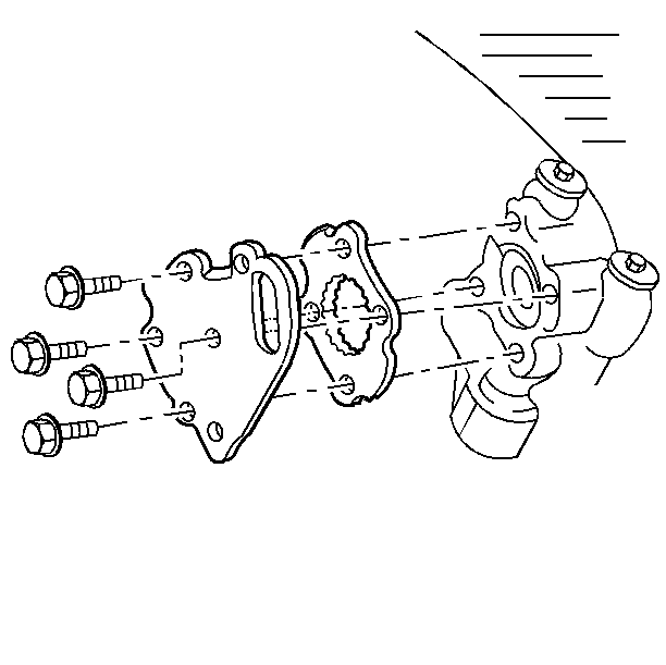
- Remove the electrical connection from the oil pressure switch.
- For vehicles equipped with automatic transmission, remove the transmission fluid level indicator tube assembly from the exhaust camshaft cover and the position aside.
- Disconnect the timing chain housing at the exhaust camshaft housing but do not remove from the parts from the vehicle. Refer to Timing Chain Housing Replacement .
- Remove the exhaust camshaft cover and the gasket.
- Remove the exhaust camshaft housing to the cylinder head bolts.
- Use the reverse of the tightening procedure when loosening the camshaft housing to the cylinder head retaining bolts.
- Leave two bolts loosely in place in order to hold the camshaft housing while separating the camshaft cover from the housing.
- Push the cover off the housing by threading the four of the housing to head retaining bolts into the tapped holes in the camshaft cover.
- Remove the two loosely installed camshaft housing to head bolts.
- Remove the cover.
- Discard the gaskets.
- Loosely reinstall the one camshaft housing to the cylinder head bolt in order to retain the housing during the camshaft and the lifter removal.
- Notice the position of the chain sprocket dowel pin for reassembly. Remove the camshaft carefully in order to prevent damage to the camshaft or the journals.
- Remove the valve lifters.
- In order to minimize lifter bleed down, use the following procedure:
- Remove the camshaft housing gasket.
Important: Any time the camshaft housing to cylinder head bolts are loosened or removed, the camshaft housing to cylinder head gasket must be replaced.
During disassembly, ensure that the valve lifters are kept together and identified so that they can be reinstalled in the original locations. Before disassembling the valve mechanism, make a compression test and note the results. Refer to Engine Compression Test .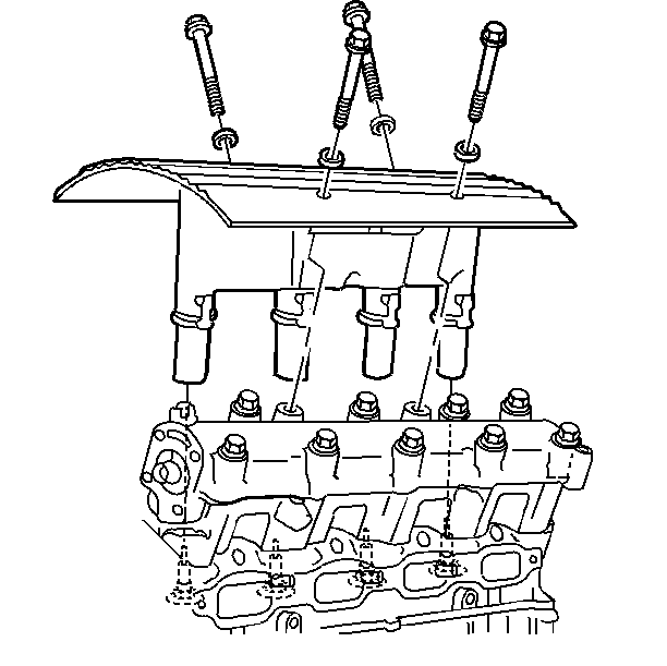
Use the tool by first twisting then pulling upward on the connector assembly.
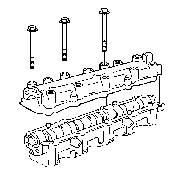
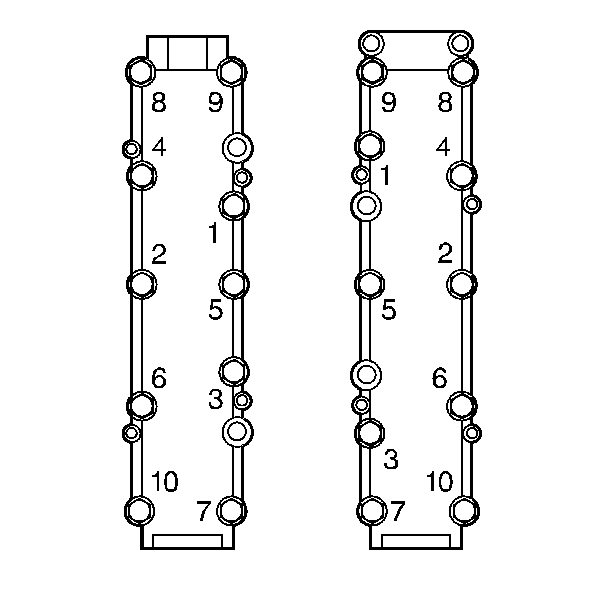
Important: Tighten the bolts in evenly in order to prevent the cover from binding on the dowel pins.
Keep the lifters in order so that the lifters can be reinstalled in the original location.
Important:
• These lifters are not serviceable. Replace any faulty lifters. • Coat the lifter with Camshaft and Lifter Prelube GM P/N 12345501
or the equivalent. If new lifters are installed, add the Engine Oil Supplement GM P/N 1052367
or the equivalent to the engine oil.
| • | Store lifters upside down (the camshaft contact surface down) on a level surface. |
| • | Store the lifters submerged in clean engine oil. |
Important: Ensure that the camshaft housing alignment dowel pins are in the cylinder head prior to installing the housing.
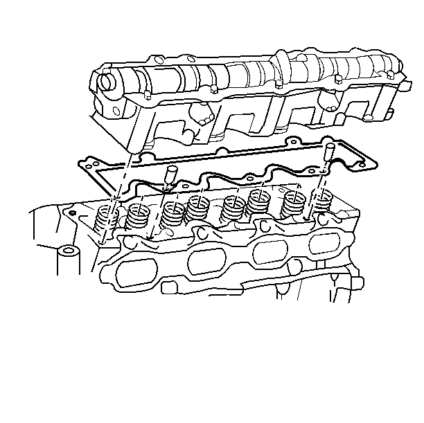
Installation Procedure
- Install the camshaft housing to the cylinder head with a new gasket.
- Loosely install one camshaft housing to the cylinder head bolt in order to hold the housing in place.
- Install the lifters into the lifter bores.
- Lube the camshaft lobes and the journals with the Camshaft and Lifter Prelube GM P/N 12345501 or the equivalent.
- Install the camshaft in the same position as when removed.
- Install the new camshaft housing to the orange camshaft housing cover seals into the cover.
- Remove the bolt holding the housing in place.
- Apply pipe sealant GM P/N 1052080 or the equivalent to the camshaft housing and the cover retaining bolt threads.
- Install the camshaft housing cover to the camshaft housing.
- Use the J 36660-A , in order to install the bolts.
- Install the timing chain housing to camshaft housing and the timing chain. Refer to Timing Chain Housing Replacement .
- Install the exhaust camshaft housing cover and the new gasket.
- Install the transmission fluid level indicator tube assembly to the exhaust camshaft cover.
- Install the electrical connection to the oil pressure switch.
- Reinstall any spark plugs boot connector assembly that stuck to a spark plug, back onto the ignition coil and module assembly.
- Locate the ignition coil and the module assembly over the spark plugs.
- Push straight down.
- Clean any lubricant that is present on the ignition coil and the module assembly to the camshaft housing bolts.
- Apply Pipe Sealant GM P/N 1052080 or the equivalent onto the ignition coil and the module assembly to the camshaft housing bolts.
- Install the electrical connector to the ignition coil and the module assembly.
- Connect the negative battery cable.
- If new lifters have been installed or the lifters bled down while the engine was disassembled excessive lifter noise may be experienced. This is a normal condition and no engine damage is occurring. Use the following procedure in order to purge the air from the lifters:
- Start the engine and inspect for leaks.

Sealer is unnecessary.
Important:
• Used lifters must be returned to their original position in the
camshaft housing. • If the camshaft is being replaced, the lifters must also be replaced.
Notice: The camshaft lobes and the journals must be adequately lubricated or serious engine damage will occur upon start up.
The timing chain sprocket dowel pin should be straight up and line up with the centerline of the lifter bores.
Sealer is unnecessary.


Notice: Use the correct fastener in the correct location. Replacement fasteners must be the correct part number for that application. Fasteners requiring replacement or fasteners requiring the use of thread locking compound or sealant are identified in the service procedure. Do not use paints, lubricants, or corrosion inhibitors on fasteners or fastener joint surfaces unless specified. These coatings affect fastener torque and joint clamping force and may damage the fastener. Use the correct tightening sequence and specifications when installing fasteners in order to avoid damage to parts and systems.
Tighten
| • | Tighten the camshaft housing to cylinder head bolts to 15 N·m (11 lb ft) + 90 degrees. |
| • | Tighten the camshaft housing cover to camshaft housing bolts to 15 N·m (11 lb ft) + 30 degrees. |

Tighten
Tighten the bolts to 15 N·m (11 lb ft) +
30 degrees.
Tighten
Tighten the bolt to16 N·m (12 lb ft).
Important: Do not compress the lifter plungers using a vise or other tool. This will cause more air to enter the lifter assembly and will take more time to bleed out once the lifters are installed.
| 22.1. | Start the engine and allow to warm up at the idle for 5 minutes. |
| 22.2. | Increase the engine speed to 2,000 RPM until the lifter noise is gone. |
| 22.3. | Return the engine to idle for an additional 5 minutes or perform a road test. |
